wanted - moto giro bike

Jason

thanks for the info re Gilera's in Argentina. Spent some time on their Gilera Forum using Google translate. Several people on the 150 technical part of that forum asking about crank/cam timing without any timing marks. Best answer seems to be set crank at TDC and "center" the cam so both lobes are equal, bloody hell. I am going to make my own timing marks when I get back to the engine, before I pull the crank.

Steve B, thanks for details re industrial chain,going to take my digital caliper and the rusty chain to my local transmission and bearing supply store. Oddly enough I had already found the Nitro Chain web site and sizing charts, just confused the heck out of me, will ask at the bearing shop for the indutrial cahin size you suggested and measure from there.
 
I'd visit your friendly bearing shop with calipers in hand and ask for some 08B roller chain.
If Batto's interpretation of the chain size being 1/2" pitch and 7.8mm wide is correct (and the bugger is rarely wrong) your bike may indeed have been designed to use a 1'2" x 5/16" (08B) industrial chain that was available in 1957. Although Regina were making motorcycle chains as far back as 1939.

Anyway, you'd be best to avoid using an industrial chain these days. They're nowhere near the quality of purpose built motorcycle chains.

The motorcycle equivalent of an 08B industrial chain is a 428. Same pitch and roller diameter but slightly wider roller.

The difference in roller width is 0.19mm (7.94mm for 428 vs 7.75mm for 08B) so it makes bugger-all difference in any practical sense. It just means that a 428 chain will have slightly more clearance between the chain side plates and the sprocket than a 08B. I suspect the 428 was designed that way on purpose for motorcycles to allow a bit more clearance for road grit to be flung out from between chain and sprocket.
 
Good stuff Cam, 428 sounds promising although I suspect a good quality 08B industrial would be equal or better than anything that was around in period anyway. :) There is a good amount of clearance in bike sprox normally, and the thickness of them seems to vary a bit. A quick measure in the shed saw my 530 chain 9.7 inside and the sprocket 8.9 wide. Either way, it seems unlikely that 0.2mm difference in width is going to matter.
Great project Paul, I'm enjoying the ride!
 
thanks Cam and Steve

I downloaded the roller chain measuring chart from the Nitro website, measured all the rusty chain bits carefully, and came to the same conclusion, a 428 motorcycle chain should work. In this case, 60 links. Will order as high a quality 428 chain as I can locate to harness all 7 raging horsepower.

my new 30 ish liter ultrasonic tank is big enough to accept the engine case half (with cylinder studs removed), dropped in the first case half tonight, ran it with the heater on until the water/cleaning solution was smoking, and the crank bearing and the trans bearing then came out of the case easily. The crank end bearing is a 6304, need two of them. Have not figured out what size the trans bearings are yet, but I will.

Now going down the rabbit hole of what bearing brand makes decent quality bearings these days? ANYONE? Both the crank bearing and the trans bearing I have out are "crunchy" even after a thorough cleaning, going to replace all bearings and bushings and seals "while I am at it".

I need the crank cases bare anyway for repair and then cleaning and polishing. The one side engine case has a hole broken in it above the dry clutch, looks like from a broken drive chain at some point in its life, not sure what case repair will be suitable.
 

Attachments

  • crank bearing 1.jpg
    crank bearing 1.jpg
    83.3 KB · Views: 21
  • crank bearing 2.jpg
    crank bearing 2.jpg
    91 KB · Views: 21
Most of the bearings I seem to buy these days are NTN. Haven't had any problems with them.
For the bearings going into the case recesses, you need C3. That's the biggest clearance available in that bearing, which is appropriate for one with an interference fit.
 
I had my riding buddy Francesco translate the relevant portions of the Italian language Gilera manual. No information of timing of cam to crank. So, charging ahead into the breach, I made my own timing calculaltions and mark, and started dis assembly. Taking lots of photos as I go for reference for eventual re assembly. The cam gear has a punch mark but it does not correlate to anything I can see, bloody hell.

Going to have to obtain another set of blind bearing pullers, my last set did not survive last years garage fire. EDIT, bloody hell, just went to order a replacement blind bearing puller set from Snap On, my recently fire destroyed Snap On set I had purchased around 1978, I had no idea of current prices (thousands!!!), just ordered a likely Chinese made set for $100, will be content with the cheap $100 set as long as it gets the bushes and bearings out of the Gilera cases even if I have to throw the cheap blind bearing puller set out after a couple of uses

Some new to me style of loose bearing rollers in a couple of the gears I have removed, never seen there like before, going to be interesting to see if I can source them with new races.

Couple of photos
 

Attachments

  • Gilera crank.jpg
    Gilera crank.jpg
    92.5 KB · Views: 36
  • Gilera crank 2.jpg
    Gilera crank 2.jpg
    103.5 KB · Views: 32
  • Gilera crank 3.jpg
    Gilera crank 3.jpg
    93.7 KB · Views: 32
  • Gilera crank 4.jpg
    Gilera crank 4.jpg
    102.7 KB · Views: 34
Last edited:
Referred to as crowded rollers I think Paul. At least they can be fully disassembled and cleaned, so unless they're worn they might be fine to re-use.. Caged roller bearings are a bugger since they're hard to clean properly, I've never succeeded getting one to run smooth after cleaning, always replaced.
 
I hate those loose bearings, especially when used on steering heads. One would always disappear when assembling them.
 
For cam timing, if you place something flat across the tops of both lobes and have that dead level with the head surface at TDC (overlap), your timing will be ok to use, and one tooth difference shows clearly. On a single of course you will then need to mark it for compression stroke. I know of engineers who have used this method on other engines. You can also check clearance valve to piston before buttoning it up. This method looks a bit challenging from the pics of how your cam sits inside the cases, but should be possible.
 
Hi Tippie

I am mulling over your explanation. My initial thought is that I have to time the cam to the crank and close the cases before I can install the cylinder to establish where the head surface actually is. Splitting the cases again to alter/correct cam timing is something I would prefer not to do.

I am also not clear on how to place something flat across the tops of both lobes to have that dead level with the head surface, as the cam lobes are rotated 90 degrees from where the head surface will be once the cylinder is installed?

Anyway, lots of time to mull this issue over, will be a few days for the blind bearing puller set to arrive, then have to finish stirpping the cases, source all the replacement bearings, clean up the cases etc before I worry about re assembly.........:confused::confused: I still have some other dis assembly issues to figure out as well.

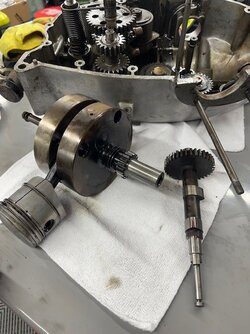
I did take lots of photos of the location of the cam lobes to the drilled holes in the crank and made some marks so hopefully things will line back up, we'll see when the time comes.

Steve

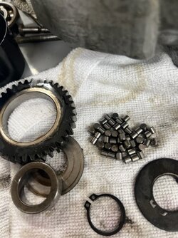
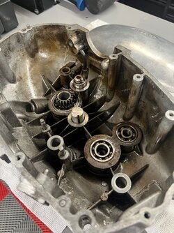
"crowded rollers", hmmmm, the inner race is pressed onto a post, the outer race is the inside of the gear, then there is a top and a bottom, both flat washers each with a locating tab to prevent them from rotating. Unless I can source brand new gears for the two gears (together with matching inner races) with this roller arrangement, I suspect I will try to find new rollers and call them good..... The various bearings in the engine cases are all "crunchy" and have to be replaced but the crowded roller units actually seem decent, fingers crossed.

My planning may be a little ambitious, but if I get the frame and all the other painted parts back by end of February as promised I am hoping to have this bike re assembled and running by mid May so I can start the "sorting" process. If specialty Gilera gears and races have to be sourced from Italy with long supply and shipping delays I will likely reuse those two "crowded roller" gears , especially if I can at least source the loose rollers locally.

Paul LeClair
 
Is that an oil ring on the piston skirt, below the gudgeon pin? Isn't that diesel engine practice?

Cheers,

bazzee
yes, that is a fourth ring below the piston pin, apparently lots of the older engines use this. Anyway, seeing lots of them in my hunt for a suitable new piston and rings, stock bore is apparently 60.0, someone has fitted an apparently previously used ASSO piston in 60.4 that it appaers the engine has never been started with. I did a kick over cold compression test before dis assembly, I don't know if 120 psi is good or not? If that is good I may just reuse the piston/rings I already have, although I am investigating how much larger a bore size I can safely go to, I am seeing likely pistons in the 61 + mm range listed for sale in Italy.

Parts searches for the old Gilera have been interesting, there is a lot of overlap with Laverda parts from various of the suppliers I have not investigated before. Particularly impressed with http://guzzino.com/
 
Regarding cam timing, did you measure the lobe centre, or opening closing positions before disassembly? Very easy with a pushrod motor as you just set 1mm pushrod lash and note the deg the pushrods tighten/free up for the opening closing points. That would at least give you a reference to where it is now.

All engines need vaguely similar cam timing, so in the absence of any information at all I would start with shooting for lobe centres of about 100/100deg and go from there. Single cam, so your lobe separation is set, so maybe set the inlet at 100 and see where the exh lobe ctr ends up. If it's 70 or 130deg, then try another position that evens it out a bit.

The good news is that in the process, you will become the world's #1 Gilera 150 engine assembly/disassembly/tuning guru. :D
 
Hi Steve

yes, I measured everything three times and marked everything. Even then I am resigned to splitting the cases at least once more......;)

I am now as far as I can go with engine dis assembly until the repalcement blind bearing puller set arrives. The one crank bearing has a gear inset into it, may be interesting removing that. All the bearings (except one) are quite "crunchy", so just going to replace them all with new. Similarily, I have three broken off bolts to deal with, but waiting on my Amazon order of left hand drills etc.. Will try to drill/tap them out, before resorting to firing up my brand new MIG and welding nuts to them...:eek::eek:

Anyone have any sugestions on current best practices on cleaning/polishing the engine cases, cylinder head, etc.? The engine cases in particular are pretty dinged up, and the head and other bits are filthy. I would like to get the engine cases smoothish and shiny, the rest I just need clean. Both internal halves of the engine cases have internal oil passages that I really don't want to get abrasive grit into so I am not that keen to vapour blast the cases

Couple more photos of progress. SInce the photos I have removed the last couple of studs so the cases can completely submerge in the ultrasonic tank, and yes I have also since drained and refilled the cleaning solution, amazing amount of crap came out of the cases and other parts, there was quite a layer of gritty filthy sludge in the bottom of the ultrasonic, and I am not finished with the cleaning process, just starting again with fresh solution.
 

Attachments

  • motor 1.jpg
    motor 1.jpg
    94.7 KB · Views: 27
  • motor 2.jpg
    motor 2.jpg
    93.9 KB · Views: 27
  • motor 3.jpg
    motor 3.jpg
    100.3 KB · Views: 27
  • motor 4.jpg
    motor 4.jpg
    77.3 KB · Views: 27
Will try to drill/tap them out, before resorting to firing up my brand new MIG and welding nuts to them...
I'd be inclined to do it in the reverse order. Try the welding method first. I've found that the heat and subsequent shrinkage after welding tends to loosen the threads and they come out easily. If there isn't room to weld a nut, just weld anything that you can get a grip on, but make sure there's room to turn it. I made that mistake once. Welded a bit of flat bar onto a broken stud. It turned the stud OK when I went to unscrew it, but I had a bit too much angle on the bar and it only went about half a turn until it hit part of the case.
 
Back
Top