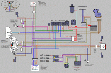
wiring diagram

Given that you have plenty of fuses (6 is more than the average Laverda) it would be good practice to not run high and low beam through the same fuse. If they're on a common fuse and something shorts out and blows the headlight fuse while you're doing 120kph at night, you'll have lost both beams. If they go through separate fuses, you may be able to switch it onto the other beam to get you home.

Headlights and ignition are probably the most crucial components so they each should have their own fuse. So with ignition, high and low beam makes 3 fuses. You can temporarily live without pretty much everything such as like horn, indicators, brake light, GPS, hand grip heaters, electric underwear, even the charging system. So it wouldn't matter too much if all those other ancilliary devices are grouped together on another fuse. By that logic 4 fuses would be enough. 6 is luxury, 8 is overkill!

Cheers,
Cam
 
Good point Cam re the the high/low beam. So I'll go 1- main
                                                                      2- ignition
                                                                      3- low beam
                                                                      4- high beam
                                                                      5- feed for switches
                                                                      6-  brake light, horn, turn signals
Sound ok???
Cheers
Rob
 
Hey Drinko,
Good input, but I'll stay with the plan and run them through the fuse box for several reasons, mainly, can't pop down to Jaycar to buy inline fuses so have to have them sent which adds to the cost of everything I buy. I also don't ride at night so having mega headlights isn't a priority. As the boys say, by 5pm you should be at your destination with a beer in ya hand.
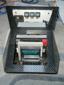
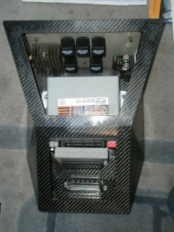
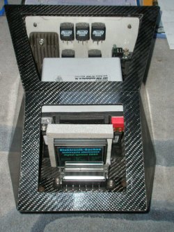
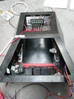
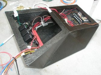
Here is a couple of shots of the electrical box with all components ready to be wired up
 

Attachments

  • P9081371.JPG
    P9081371.JPG
    114 KB · Views: 32
  • P9081372.JPG
    P9081372.JPG
    110.9 KB · Views: 22
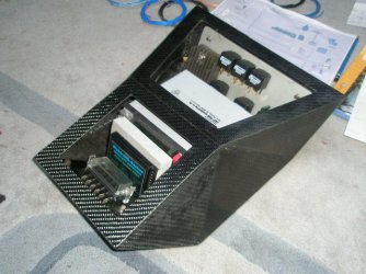
couple more. Hope the smaller battery can cope with the H/C motor!! No room to go bigger.
 

Attachments

  • P9081373.JPG
    P9081373.JPG
    113 KB · Views: 17
  • P9081374.JPG
    P9081374.JPG
    117.5 KB · Views: 30
Very neat. It was only with the last picture that I could make sense of it.
Where will that be mounted?

Superb job by the way!
 
1000/3C_Stefan said:
Looking on your pictures there seems not much room left for the spade connectors on the fuse box and 3 relais in the top row. Try to avoid sharp bends in cables right behind spade connectors when wiring it up.

Regards,
Stefan

Hi Stefan, what something like this :o The bends aren't as bad as they look, the wire leaves the terminal straight before taking a right angle bend. As for the relays you suggested, too late I've brought everything and they're installed.
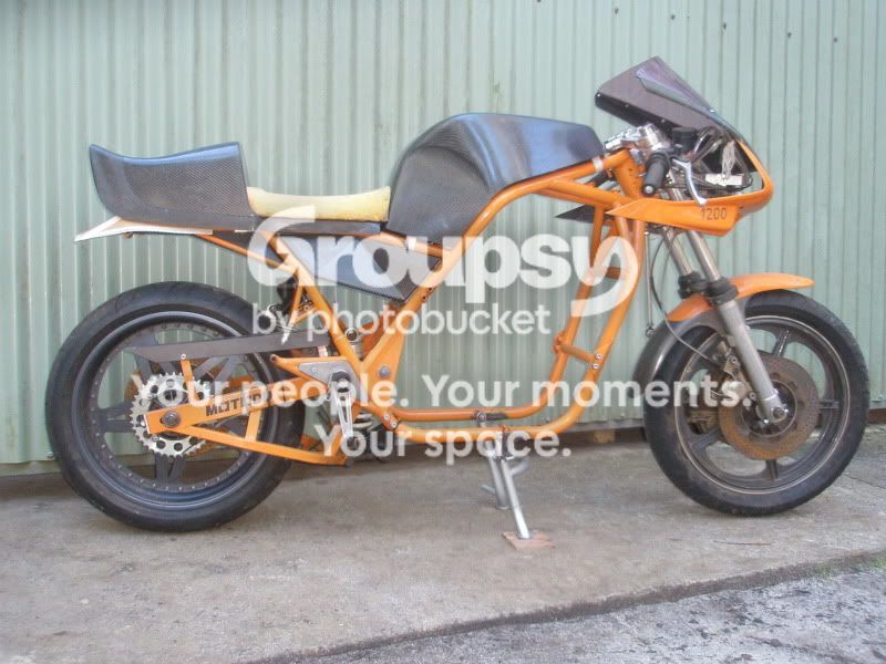
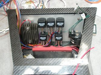
Grant, it's the box that sits in the triangular frame section. Once finished it will be water proof.

P7211258.jpg
 

Attachments

  • P9091371.JPG
    P9091371.JPG
    115 KB · Views: 35
  • P9091372.JPG
    P9091372.JPG
    108.9 KB · Views: 23
  • P9091373.JPG
    P9091373.JPG
    115.4 KB · Views: 26
Here's a question, the neutral light wire goes from the neutral switch to the neutral on the dash, how does it get power??
The bulk of the wiring is done, just need to tidy it up now. Worth spending the money on a decent set of crimpers too.
Using the Thin Wall PVC cable the bulk of the harness going up to the head stock measures 12mm dia. Less than half the size of the original.
So far so good!!
 

Attachments

  • Wiring Diagram Original.gif
    Wiring Diagram Original.gif
    127.8 KB · Views: 30
Hey Stefan,
My R/R doesn't have the gen light/voltage sense line.
Only have 6 wires, 3 yellow from the Alternator, 1 to battery + via a 25amp fuse, 1 to ignition switch and 1 to battery earth.
Would dearly love to have the gen light back again.
Being an electrical nunce it's all very daunting really.
Yes, it should be a cracking bike when it's finished. The last 100k km it's performed beautifully, with the latest upgrades it can only be better. can't wait to ride it again. It really is my #1 favorite bike.
 
motoddrob said:
Here's a question, the neutral light wire goes from the neutral switch to the neutral on the dash, how does it get power??
The bulk of the wiring is done, just need to tidy it up now. Worth spending the money on a decent set of crimpers too.
Using the Thin Wall PVC cable the bulk of the harness going up to the head stock measures 12mm dia. Less than half the size of the original.
So far so good!!

Power is constant (when key is turned on) to the instrument cluster and hence neutral light. The wire from the neutral globe to the neutral switch is the earth wire and that circuit is closed when the gearbox is in neutral meaning the neutral indicator light will come on, put the bike in gear and the switch is opened meaning the neutral light is now not connected to ground.

Probably explained it poorly. ::)
 
Generator light is not easy to organise if there is no gen light output from the RR. There's a little bit of electronic jiggery-pokery necessary. The voltage sense line won't do it.

I fiddled around for a while trying to make a simple circuit external to the RR that would drive a generator light, but without any great success. The important word in that last sentence is "simple" because I'm pretty useless at designing electronic doohickeys. However, despite my amateur fumbling, I actually got a couple of different solutions to work, but they weren't 100% satisfactory or reliable. I hadn't quite given up on the idea when progress on my own solution was rendered un-necessary because John Wilson came to my rescue with his version that actually worked perfectly.

He sent me one of his VM (voltage monitor) devices, which basically mimics the operation of the old voltage regulator driven generator lights that we know and love.

Only problem is that John isn't building any at present (I think the VM he sent me was one he prepared earlier). Although he did say he'd conider buying a bunch of components and doing a production run if he thought he could sell them. Perhaps if there are enough people on here glamouring for a working generator light, we could coax John out of retirement.

Cheers,
Cam
 
That makes sense Davo, looking at the BTZ diagram there is a hot wire that goes from the fuse and connects the stop light switches and ends up at the neutral and gen lights in the instruments.
On the diagram I'm using, if I was to use the + feed to the H/bar switches and connect to #5 on the gauge's cluster as Stefan suggested,
should work?? What ya reckon Stefan??
Electrickery really fucks with my brain!!

Cam, I do remember John saying he had a solution to the gen light, didn't follow it up, think I should send him an email!

Cheers
Rob
 
OK ...  Idiot-proof instructions for the electrically challenged:  ;)

There should be two wires hanging out of the bottom of the neutral light lamp-holder. Take a feed from #5 on the instrument connector block in your diagram as Stefan suggests. That feed goes straight to one of the neutral light wires. The other neutral light wire goes to #3 on the connector block. That's it - job done!

If you have non-standard instruments and your neutral light lamp-holder doesn't have 2 wires (ie: uses the instrument body as earth), then it's not quite as simple. Let us know if that's the case and I'll give you a solution for that scenario.

Cheers,
Cam
 
2 wires Cam so clear as mud!!

Thanks Stefan also for your input.

With our collective knowledge we should be able to solve the worlds problems :D

Cheers all
Rob
 
Just had a look at the original wiring diagram, neutral light should have a black and a red/green wire. The black is the +ve feed (from 5 on your diagram) and the red/green is the lead to the neutral switch (connect to 3 on your diagram) although it really doesn't matter as they are just feeding through a globe, it's just nice to keep all +ve feeds the same colour eh?

Where your diagram is confusing is that it doesn't show the neutral switch going to earth.
 
I think I was running one of John Wilson's generator indicators at one time.That's if it was a run of LEDs that lit up progressively like a gear change light used in drag racing as more current was generated.John was working on a trick 3 phase RR that was capable of charging a battery from my early weak as piss alternator at the time and I was the Guinnea pig.I think the RR was a dead end,ended its life with a big spike a few times.I got home with the help of the massive 950 Odyssey Battery I was running at the time.The Gen indicator did its job by telling me the battery was not charging.Someone else found a similar gadget on E Bay a while back,it was even simpler than Johns gadget.I think it was one light that either got brighter or changed colours.
 
Someone else found a similar gadget on E Bay a while back,it was even simpler than Johns gadget.I think it was one light that either got brighter or changed colours.

eBay item 150479033981 and now 160638470365 too - spoilt for choice  ;)
 
Rob, looks to me like you have done a great job.
                One concern is you said you used thin wall pvc wires. Is it automotive grade, it needs to be. Motorcycles in particular are a very harsh enviroment for exposed wires. In the last picture you have a bunch of wires zip tied together I hope you plan to put these in a protective sheath/cover. The wires need a protective cover from oil,petrol, heat, vibration, uv rays, rain etc. If not protected they will have a very short life.    Cheers Dave
 
Yeh Dave, it's the modern automotive cable most manufacturers use these days. It's half the dia. of the old stuff. All the wires that go up the the steering head fit into a 12mm sheath. All wires will be sheathed except the bundle that live in the box, and that will be water proof once I make a couple of lids for it.
 
Back
Top