About my Jota 81's

Xav

Hero member
Location
France
Hi

For my 1000 Jota of 81 ?full?, A/C 4C, ignition Bosch BTZ and ND, I do not find the adjustments basic. (I posed my problem on the French forum. Grant and Redax5 brought answers to me (thanks ...))

As Redax5 explains it to me : "Is a little difficult on the 81's to strobe them as you don't really have anything to strobe against apart from the marking on the nut".

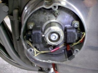
Look at the photographs : The marking on the nut is "strange?. It is curved. And I have two marks on the engine crankcase and that of right is an arrow ??? 

I try to keep my Laverda "mechanically origin?.

In France, Jota 81 was diffused very little, and the data and manual technical are especially on models 3 CL (A/C A 11 or A 12 and ignition Bosch on the right (Bosch HKZ))

If a happy owner of this formidable generation had the basic values and adjustments or all manual posterior workshop with the technical manuel of 1977?  I'll be pleased

Xavier

 
The 81s are easy enough to stobe    ---- first of all you need to confirm that the top dead centre mark is correctly positioned and clear enough to see------ then you need to mark the top dead centre position on the inner primary case itself.  ---- this will be your top dead centre reference mark ----because the raised mark on the trigger stator plate will move with the plate and will appear to negate any adjustments.  It doesn't actually negate the adjustment ---it is not top dead centre anymore but your mark on the inner primary case is your reference when joining the camchain or aiming your strobe.
There isn't much movement on the stators slotted holes and everthing is positively positioned so there is only a small amount it can be wrong by
I often use a slightly different method.  Mount a strip of metal between the front two of the three trigger cover screw  (broken coil bracket / meccano etc)  locate TDC and mark the metal strip to align with a point of the hexagon on the rotor. It is easier to be accurate with this method.
It is important that your trigger gaps are set nice and square with the rotor and you should aim for equal trigger gaps.
 
Hi Xavier,

An easy and reliable method of making an accurate strobe mark on your ignition rotor without the aid of specialist tools is the following;  You will need a vernier, dial or digital caliper with depth guage.  Remove sparkplugs, turn engine till outer pistons are well down in the bores.  Insert caliper in the LH plug bore, rest caliper body firmly on the edge of the plug bore, hold parallel to cylinder and lower the depth guage probe.  Turn crank forwards via rotor hex slowly so the piston pushes the depth guage towards and over TDC.  Keeping the caliper in position, take and note the reading or zero in the case of digital caliper.  Still holding the caliper in place, turn crank back for 1/2 revolution, push depth guage back into the bore.  Now turn the crank forward once more till you reach the point 7mm before your previous reading.  You can now mark your rotor and primarycase, not the trigger base plate in this position.  You now have an accurate mark to strobe your ignition at 32?BTDC.  The procedure is easier with a helper holding the caliper only, but with a little practice, it can be executed single handed.

The trigger base plate is positioned by a spigot on the primary housing cover, a small chisel mark on this spigot and a chisel mark on the rotor can be highlighted with a stroke of a felt pen, which is easy to see when strobing.

The other, imho, more complicated method involves using a piston stop and degree wheel.....as described by Stevio.

The caliper method is just as accurate..... I've checked and double-checked several markings with both methods, usually less than 0.5? difference........... taking into account that crank phasing is often off by as much as 5?, that's as perfect as it needs to be! :D  It is often overseen that an accurate TDC isn't really needed for strobing, as you will be adjusting to a 32? mark.  THIS, on the other hand, DOES need to be accurate!  The stock igintion timing is specified as 32?BTDC, and this is what you will need as a baseline for future adjustments.  Piston stops and degree wheels are not typically found in Joe Averages' toolbox. 

As Steve descibes, trigger gaps can influence actual individual timing.  Make a mark for the centre cylinder and check this as well. 

HTH,
piet
 
i had a problem when timing my jota i ws using a state of the art snap on timing light and just couldn't get the timing right i ffffed about doing all sorts then asked stevio the snap on light was for cars which the ignition runs off the camshafts which of course runs at a different speed to the crank after altering it it ran great cheers stevio
 
With a 81 Triple it is probable that the Factory TDC marks are correct unless the primary case has been changed -----in which case if you have a delay type strobe you don't need any other marks.
if you have a fixed position strobe you can use the accurate markings on the stator plate to position your 32 deg mark on the primary case ---or on the rotor if so desired.
If you suspect the engine has been "messed with"  you might want to verify more than the timing marks,  If you doubt or for some reason don't have the original cast in  marks they can be accurately checked or produced with a school kids protractor.  IMHO it can't get much simpler or need less kit. 
 
Attached link shows how we do timing set ups
helps having your own machine shop to make all the required adaptors for LH and RH ignitions.

http://laverdapedia.com/index.php?title=Timing_disc_%281000cc_series_1_and_2%29

Snap On timing light is, well, a timing light.
It couldn't give a rats if it was timing a car, boat, bike, clothes line, etc, all it needs is a spark.
It flashes every time it see a spark, which on our Laverda's, is on every stroke of the crank as they run wasted spark ignitions.
When you use this style of timing light you need to 1/2 the reading that you have, so for 32 degrees, you are looking for 64 degrees.
Same at idle, 8 degrees will register as 16 degrees.
I would not swap my Snap On timing light for anything.

Tchau
Red


Hey Red, I'll swap my gold plated snap-on timing light for one of your 120 engines :P

Terry
 
Here is the photo that I tried to upload yesterday

Regards

Xavier
 

Attachments

  • Ignition.JPG
    Ignition.JPG
    24.5 KB · Views: 125
make sure you have the right (and same on both pickups...) gap between the pickup and the rotor... I think to remeber right setting is 0,2mm, but am not sure. Piet or Stevio to correct me, please.
 
I have said this before....

  Inductive timing lights dont seem to work without a small "Jockey lead"  between the plug and lead.... My Kent-Moore Km 4142 works a treat with a bit of broken plug and HT linked to the plug


The actual gap can be varied to adjust the point at which the ignition steps up on to it's advance curve. The exact output of the triggers can vary but the pairs (or sets of 3) are usually pretty well matched and so matching the gaps will usually (but not always) match the advance step of the two (or three) ignition channels.  -----absolute accuracy can be achieved by using more technical means such as a dual trace oscilloscope  but previous results of such tests have demonstrated that , in most cases accurate matching of the gaps will in fact produce the desired results.
The closer the gap the earlier the step.
You do not need a strobe to reveal the step point (but it can be useful)--- you can hear it if the low end set up of the carbs is reasonable.  --- just  open the throttle very slowly and listen to the engine. The speed of the engine will suddenly increase when it advances.
The CDI and the BTZ systems are not actually capable of supplying the sparks at exactly the right time throughout the operating conditions of the engine so you can only really ever attain the best compromise.  Sometimes it is useful to , for instance, time the step to help correct (or cover) a glich in the carburation
A rider who spends much time in heavy slow traffic may find it useful if the step appears a little further up the rev range  which will increase the range of throttle openings he can use in heavy traffic without the ignition timing jumping about .
On the other hand a tired CDI system may benefit more from closer gaps to assist starting.
I have had 3 snap-on strobes they worked well enough (using the seperate  spark canceller) but none were as reliable, rugged or bright as the one I have now which has pushbotton  spark cancelling
 
Hi

After the ignition, I'm back with a new technical question

I have seen various sources refer to inlet clearances anywhere between 0.10 mm and 0.25 mm, exhaust clearances anywhere between 0.25 mm and 0.35 mm

I have a Laverda 180? serie 2,  with Cam 4/C
I have seen for this model ;
inlet  0,15 mm
Exhaust  0,25 mm

Is that correct ?

Thanks in advance

Xavier
 
I also try to stay at the lower limits of the tolerances, but inlets can be 0.20-0.25, exhausts 0.25-0.30, independant of which cams are fitted.  Boils down to which shims you have to hand and if you're too lazy to grind 'em to the size you really need..... :D

piet
 
It was perfect ...
Inlet :  between .15 mm and .20 mm
exhaust :  .20 mm to .25 mm
The engine purrs

Thank you gentlemen

Xavier
 
A word of warning.
If the gap is too small, and I am not sure if 0.15 is too small for the inlets, the engine may run quietly, but the valves may not close fully, which in itself will give problems in the long term. Also there is a danger of more intimate contact between cam lobe and cam follower (bucket), which could lead to premature wear of the follower surface.
I bought a secondhand Laverda once and I could not get the valve clearances set accurately.
It turned out the surface of the cam follower was not flat, rather sort of bowed/ worn. The conclusion at the time I was told was due to too tight valve clearances, removing the oil film.

Just so you know.
 
Grant,

0.15mm works OK for the inlets in normal road use.  Wouldn't recommend it for track use with the entailing higher head temps, though.

I've gone down to as little as 0.10 in, 0.15 ex without ill-effects.   It was the constant checking that caused me to go back to factory specs, you don't have a great safety margin with smaller gaps, but the engine does become very quiet upstairs.   Less than 0.5-0.8mm will definitely lead to slight bother on the ex side.... :D

piet
 
Back
Top