750 points and electronic system?

The max advance "A" mark on an SF is 40 degrees, which is a lot, and many bikes are prone to pinking under load depending on fuel and other tuning issues. Static timing is set at PM (top dead centre), and using these marks accurately it is best to mount a pointer of some sort close to the mark. It is some distance to the mark on the crank case from the starter clutch, and regardless, check the accuracy of the PM mark against the piston at TDC. If you set static timing to 5 deg BTDC then the full advance is 45. It is possible also to reduce the range of advance in the centrifugal unit with a dab of weld if you want less max advance. The thickness of material on the contacts in your picture seems fine, the surface needs to be as perfect and flat as possible, can be achieved with a fine sharpening stone with the points dismantled. I think the platinum contact pads are somehow soldered (or similar) onto the backing metal, not riveted.
 
Condensers come from the same place as the points so easy too buy both from same place , just a point
You need too remove all parts from the back plate , remove the spring point as this now has it own insulation built in ,
And knock the brass pin out of the back plate of the point leaving you with a hole that goes over the pin on the laverda back plate , may have to tweek that hole a little .
 
you are dead right Nickdav7, my Egli has not run since 1980, its last trip taking me to the IOM TT of that year, luggage space was at a premium.
CLEM
 
So it's the Interloper w/ those connections to use, or is it the Remax points assembly that works? I contacted a vintage VW points supplier w/ the Bosch ZVUB1Z1Z stamped number, but they oddly couldn't help me. So far I've set the .4mm gap and used a small light hooked up per the Green Book, and it flashes @ 1" before reaching the TDC mark while rotating the crank clockwise. So I take it that the timing is slightly retarded?
 
So it's the Interloper w/ those connections to use, or is it the Remax points assembly that works? I contacted a vintage VW points supplier w/ the Bosch ZVUB1Z1Z stamped number, but they oddly couldn't help me. So far I've set the .4mm gap and used a small light hooked up per the Green Book, and it flashes @ 1" before reaching the TDC mark while rotating the crank clockwise. So I take it that the timing is slightly retarded?
The Bosch points are unobtainable.
Timing is slightly advanced if it flashes before the TDC mark whilst static.
Paul.
 
The whole world is suddenly awash with points for 750 Laverda.
There is absolutely no need to make a good bike unreliable by sticking an electronic ignition on it.
Paul
 
Not always enamoured with electronics, given its my field since 1966, analogy of musicians declaring with lots of cash, thermionic valves sound better than transistors, various designs. Plain fact remains they are different and do sound different, given at times the gap is not wide as designs dictate, clever folk involved.

The MTBF of points wearing out/centrifugal mechanics out of tolerance, and the near zero MTBF ( well designed electronic hardware/firmware ) expose that for certain owners, the electronic systems are more than suitable, over on the other mount there is a dedicated contra narrative, atop, a man of much conviction, whom rode in on a points laden vehicle and like as not, able to ride back home, even with a roadside stop over to open the gap... a gap that is wide indeed, as wide as the two narratives.....

Await the outbreak of exact value of the "condenser" "Condensor" Leyden Jar... nee capacitor. Two jobs, spark quench and ignition coil primary return current ( and HT current in many coils ) path.... much demanded item... start the bidding at 0,2uF.... do i hear 0,4... bigger has to be better... yes? j.
 
Last edited:
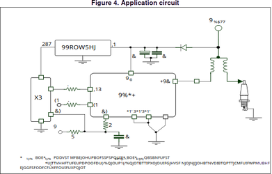
This is the correct polarity for electronic ignition Y type ignition coils, the common connection between primary and secondary windings is at Battery potential ( low impedance path back to 0V or battery negative/engine frame ).

Opposite connection polarity for points systems, one advantage of a twin HT tower coil there is no "polarity" and negative fire centre electrode can be achieved if used as a single cylinder ignition coil, whic is what i do, ie i do not use single HT output coils as a first choice, always second if i must. HTH J Use of ST data sheet disclosed, gibberish annotations from extracting pdf image.


1708200564580.png

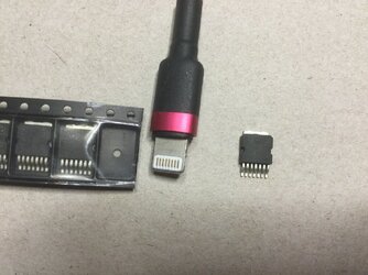
Size relevance of this 8amp inductive ignition controller, actual timing variance is done with a uP or dedicated HEI device chip, 0,8m/m soldering space, i have to hold my breath to solder with a 0,1m/m tip iron, or the fascinating short all solder tabs and then clean swipe by capillary action, all the bridges removed.... how i used to make the iis pcb in the main production days.
 

Attachments

  • IMG_0183.JPG
    IMG_0183.JPG
    134.8 KB · Views: 14
  • IMG_0198.JPG
    IMG_0198.JPG
    139.8 KB · Views: 12
Last edited:
This is the correct polarity for electronic ignition Y type ignition coils, the common connection between primary and secondary windings is at Battery potential ( low impedance path back to 0V or battery negative/engine frame ).

Opposite connection polarity for points systems, one advantage of a twin HT tower coil there is no "polarity" and negative fire centre electrode can be achieved if used as a single cylinder ignition coil, whic is what i do, ie i do not use single HT output coils as a first choice, always second if i must. HTH J Use of ST data sheet disclosed, gibberish annotations from extracting pdf image.


View attachment 88325

Size relevance of this 8amp inductive ignition controller, actual timing variance is done with a uP or dedicated HEI device chip, 0,8m/m soldering space, i have to hold my breath to solder with a 0,1m/m tip iron, or the fascinating short all solder tabs and then clean swipe by capillary action, all the bridges removed.... how i used to make the iis pcb in the main production days.
I had to look at the data sheet to decipher the weird annotations.

Potentially the microprocessor the determines the timing, 'X3' in the gibberish diagram, could be replaced by a set of points with centrifugal advance, plus maybe some circuitry to massage the signal to the coil driver. But that would be like some 'hybrid' audio amplifiers that use a valve preamplifier driving a solid state power stage.

Cheers,

bazzee
 
Indeed Barry, one application, as you describe, the ability to use a low inductance ( higher speed to saturation ) ignition coil "Current Limited" type perhaps has some advantage, in a points system.

The coil primary would be pre discharged when the points are cold crank initial movement if in the closed condition. Need a current contact wetting ( yours/my field as i recall ) pull up resistor, ie no spark until the next rise of the input pin, then a spark initiation on the falling edge, ie points closing again, dictating an inverted input signal device in the points application.... then you may as well use a HE or slotted Opto... and the cat has indeed escaped the bag, as it should..whom would spend a life in a bag... electronics... where would you be without technology... riding away on your megacycle ( Milliohm as pillion ) points powered.... for there was no alternate of that era than a Kettering system for mass usage....

Witnessed postings here over the years about the correct connection of a designated terminal or colour on an ignition coil, impetus for my recent replies and diagrams, made simple, yes i know the odd many find perhaps not so made simple and less than obvious clear....a wink here j
 
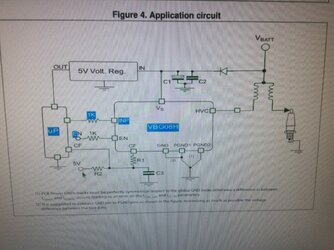
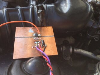
As mentioned, the ignitor had failed and was not going to fork out $150 for a replacement until i knew what are the issues overall. Took 30 minutes to fabricate a test iis ignitor and no one more surprised than me, it worked and worked instantly. The size of modern electronics is amazing let alone the actual power control and density issues overcome by these very clever modern engineers, chemical engineers.

This VBG08H is not only cost effective, it performs remarkably. The motor just purrs now. No fancy boxes for this $5 device and scrap pcb, left over resistor and diode, hidden tiny zener clamp on the input to protect the ECU from punch through. Sort a left over iis box next few days.

Bruce, the ability to transfer heat across the substrate FR4 pcb material is mind boggling, been doing it since 2000 and it still has me amazed to this day. j.
 

Attachments

  • IMG_0217.JPG
    IMG_0217.JPG
    124 KB · Views: 24
Rob, there is stage Jon ( makes a nice logo on my bass cases from 1977 onwards to today ) and Christened John for legal matters. Part of the entertainment scene, fake is good, a smile here.

This controller ic in question, as Bruce and especially Barry indicate, an inverting single transistor on the small pcb would allow points to be used and any type of ignition coil to be used, from low ohmic ( 0,7 ohms ) to 3,3 Ohm types, the low ohmic ( low primary winding inductance actually ) type would draw more from the generator/battery though would not be too high overall as you could modify the points gap for minimum off spark current demand. In any case it would be the same or less with standard 3,3 Ohm coils/points installed, added bonus no more arcing points or condensor/capacitor.

Only need a wetting current across the points say 100mA and your actual contacts would never wear out as a guide. Just address the buffer block wear and advance mechanism maintenance. Need two devices, can be on one smaller pcb and box. Yes its not vanilla points and yes your current points will last until the earth ceases... or thereabouts.

Just had a thought, given the availability of asian custom pcb manufacture, could design a points friendly dual ignitor iis board and box, dependent on how much demand, in the forum, have to be in the range 10-20 units at least to be worth the effort. Just be for twins with points however. j
 
Last edited:
Back
Top