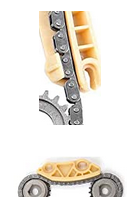
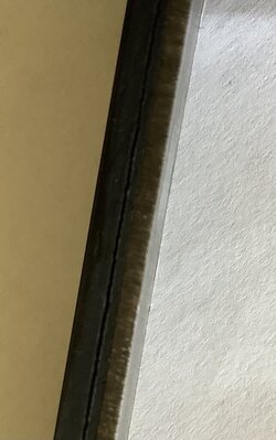
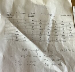
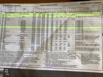
lot of good ideas so far but looking at the dimensional constraints inherent to the current architecture of the actual engine components am going to purse stronger cam chain tensioners, just a matter of custom making them
here are some answers to previous comments
Cannot use the rear leaf springs from my Chevy truck as the actual chassis is a Holden HJ Ute so springs are not 1950 Chevy anymore, they are 1974 Holden springs

I have been machining my own cam chain tensioner "wheels" now for a few years from Delrin as the standard ones got hammered flat, which backs up the theory that the tensioner blade is copping a serious hammering
Even with the Delrin wheels I still see some deformation but no where near as bad as the standard wheels
But I do like the idea of a curved blade instead of the point contact as supplied by a wheel so am going to have a go at machining a curved blade to mount on the standard tensioner and see how that works out
Valve springs, I use PAC Alloy dual valve springs and we machine our own top and bottom plates to suit, installed height is very close to standard but pressures are higher of course
A standard Laverda valve spring as supplied by Wolfgang and probably the exact same piece of kit as supplied by OCT, Andy Wagner etc has the following loads when new, when installed with 4C cams that have 9.8mm lift on Inlet and 9.1mm lift on Exhaust
Inlet closed 55 lbs, open 156 lbs
Exhaust closed 50 lbs, open 144 lbs
Allow for +/- 4-6 lbs on each figure as there are a few variables in play that affect those loads, actual free valve spring length which does vary slightly even when new, where did the valves come from and hence at what height have the Collet grooves been cut at, where is the valve seat in relation to the camshaft center line, etc
I would expect to see slightly lower values as the valves that I have custom made have their Collet grooves lowered slightly hence they increase the spring loads
I am currently running 7C cams in both engines, I do have custom made far higher lift cams in stock but need to order pistons to suit but right now am more than happy with the performance of the 7C cams
Lots of people run them down as being unsuitable but with the Exhaust and Inlet tract design that we have done to date and the amount of dyno runs we have done we have no flat spots in the power and torque curves from 3,000 to 9,000 rpm so see no reason to change them at the moment
7C cams have similar valve opening to a 4C Inlet cam, I have 9.72mm lift on Inlet and 9.62mm lift on Exhaust cam, which gives me the following loads on the PAC Alloy dual valve springs
Inlet closed 84 lbs, open 192 lbs
Exhaust closed 80 lbs, open 186 lbs
Even though these valve loads are higher than a standard engine set up with a single valve spring they are no where near what other race engines are running which can be well over 300 lbs closed and 700 lbs open for say V8 drag race motors or even a Hardly Dangerous engine
I know my mate Ollie runs way higher spring loads in the Harley race engines he builds but in saying that they are also generally Pushrod engines so operate under totally different parameters
Cam, I looked at doing something very similar to what you have drawn to retain the lower section of the cam chain blade but the difficulty I see is actually finding that "keeper slot" when the engine is assembled, cam chain blade is one of the last items to be installed and to try and find that "keeper slot" with an assembled engine is going to be character building
Though may be possible by manipulating the blade end from underneath the engine through the cam chain guide tunnel
Will keep thinking on it, have a few days as have some other issues with this race engine that need attention as well now
Must be mad to race these engines the way we do
here are some answers to previous comments
Cannot use the rear leaf springs from my Chevy truck as the actual chassis is a Holden HJ Ute so springs are not 1950 Chevy anymore, they are 1974 Holden springs
I have been machining my own cam chain tensioner "wheels" now for a few years from Delrin as the standard ones got hammered flat, which backs up the theory that the tensioner blade is copping a serious hammering
Even with the Delrin wheels I still see some deformation but no where near as bad as the standard wheels
But I do like the idea of a curved blade instead of the point contact as supplied by a wheel so am going to have a go at machining a curved blade to mount on the standard tensioner and see how that works out
Valve springs, I use PAC Alloy dual valve springs and we machine our own top and bottom plates to suit, installed height is very close to standard but pressures are higher of course
A standard Laverda valve spring as supplied by Wolfgang and probably the exact same piece of kit as supplied by OCT, Andy Wagner etc has the following loads when new, when installed with 4C cams that have 9.8mm lift on Inlet and 9.1mm lift on Exhaust
Inlet closed 55 lbs, open 156 lbs
Exhaust closed 50 lbs, open 144 lbs
Allow for +/- 4-6 lbs on each figure as there are a few variables in play that affect those loads, actual free valve spring length which does vary slightly even when new, where did the valves come from and hence at what height have the Collet grooves been cut at, where is the valve seat in relation to the camshaft center line, etc
I would expect to see slightly lower values as the valves that I have custom made have their Collet grooves lowered slightly hence they increase the spring loads
I am currently running 7C cams in both engines, I do have custom made far higher lift cams in stock but need to order pistons to suit but right now am more than happy with the performance of the 7C cams
Lots of people run them down as being unsuitable but with the Exhaust and Inlet tract design that we have done to date and the amount of dyno runs we have done we have no flat spots in the power and torque curves from 3,000 to 9,000 rpm so see no reason to change them at the moment
7C cams have similar valve opening to a 4C Inlet cam, I have 9.72mm lift on Inlet and 9.62mm lift on Exhaust cam, which gives me the following loads on the PAC Alloy dual valve springs
Inlet closed 84 lbs, open 192 lbs
Exhaust closed 80 lbs, open 186 lbs
Even though these valve loads are higher than a standard engine set up with a single valve spring they are no where near what other race engines are running which can be well over 300 lbs closed and 700 lbs open for say V8 drag race motors or even a Hardly Dangerous engine
I know my mate Ollie runs way higher spring loads in the Harley race engines he builds but in saying that they are also generally Pushrod engines so operate under totally different parameters
Cam, I looked at doing something very similar to what you have drawn to retain the lower section of the cam chain blade but the difficulty I see is actually finding that "keeper slot" when the engine is assembled, cam chain blade is one of the last items to be installed and to try and find that "keeper slot" with an assembled engine is going to be character building
Though may be possible by manipulating the blade end from underneath the engine through the cam chain guide tunnel
Will keep thinking on it, have a few days as have some other issues with this race engine that need attention as well now
Must be mad to race these engines the way we do