Redax Generator and Ignition upgrade to Laverda Jota 180 series 1

The season is drawing to a close and I am off to France on the old Beemer in November

Nice.  I did that a few times in the past and you can get some great weather and clear roads.
 
3rd year for the " Poppy run"  ...I'm staying with Dave Platt at Auchon-villers ,who is quite a character and a historian  and a biker too. He runs motorcycle tours of the battle fields...and has a soldiers perspective as he has only just left the British Army...

And so far yes...I have had good weather Reggie...Last year because of an unusual ferry timing I landed at Dieppe and rode into the Somme , just me/daughter on the back , the bike and the misty Fields of France as the sun rose...memorable.

It has now become my end of season last run out....and a nice way to pay respects..100 year anniversary of the Great War next year..

joe
 
redax5 said:
I normally bolt a small plate onto the side of the electrical box where the Bosch black box was and then stick the Sachse box onto the plate
is just behind the side cover that way and easy to get to if you wish to change curves

I found that with the SSB LiPo there was still plenty of room to stick it on the front of the tool tray, above the battery and easy to get it when you lift the seat.
 
jotajoe said:
Thanks Davo.

Didi you fit yours to the 3CL btw ? ..as against mine is a 180 series 1 Jota

joe

It used to be a 3CL until Red got his mitts on the lump  :D
 
Guys

I have a gen1 180 and have just fitted new a pair of Dyna 3ohm mini dual output coils and leads

The dual output coil for the outer pots generate a nice big spark.

The dual output coil for the middle pot isn't producing a decent spark at all, unless I add another lead/plug and earth out which obviously I dont need - this I think from reading this thread is due to the lack of earth if I am just use one lead/plug

Apart from sending one coil back and getting a single output coil, is there anything I can do to the spare coil output to produce the earth that needed ??

I thought each output on the dual output coil was independent of each other, and their earths were the plug/frame but after reading this thread, it seems not ...
 
Hi Jotaman, I’m certainly no electrical wiz but I would have thought the easiest option would to be replace one of the duals with a single output coil as you suggested.

Briefly glimpsing through the previous posting history it seems the dual output coil has some type of secondary return via the second lead thereby creating a complete “earth” cycle.🤔 the only thought that springs to my mind and again I,m no expert, is to provide the coil with its own earth as in how a single could would be wired up thereby tricking it into not needing the second lead as a return 🤔………make sense???

Apologise if talking Bo#@£ks 😁
 
if you are using a dual coil on the middle cylinder then the spare high tension lead needs to be mounted to the frame or engine

lets look at the dual coil and 1 and 3, when the coil fires, energy runs down one high tension lead, jumps the gap on one spark plug to generate the gap, flows across the engine, jumps the gap on the second spark plug and then returns to the coil through the second high tension lead thus completing the circuit
that is a very basic laymans description of how the dual coil works

Dyna mini series coils are crap but they are not your issue
 
Following on from Reds' correct description of how a dual post ignition coil functions, with a dual post you actually have galvanic isolation between primary winding and the secondary windings ( both ends of the secondary winding are electrically available via the posts ). With many single HT post ignition coils, the primary and secondary are not galvanically isolated, this is done for production purposes and not ideal design, ie cost saver going back to the kettering system and latterly points.

This galvanic isolation aids in protecting the driving electronics ( "points" to you Mr Paul, a wry smile here ) and as such is my preferred configuration for a 180 series 1 motor, two dual post coils, centre coil with one post connected to the motor or frame. Allowing swapping of coils in fault diagnosis. Some coils work better than others, cost effective were Japanese manufactured coils in the day. Trust this muddies the waters for how basic ignition systems function, looks clear to me?? Wince HTH j.
 
Yep. What red says. Connect the spare HT lead on the centre coil to an earth somewhere. Closest point available would probably be one of the coil mounting bolts. That's how my Jota is wired. It's the way it came when I bought it. It had a Witt ignition back in those days with what I assume are a pair of twin output coils recovered from a 4-cylinder Japanese bike. It's always worked OK so I never bothered changing it, even after fitting an Ignitech ignition.
For some OCD related reason it's occasionally bothered me when I lift the tank off to see a dual coil "wasted" in that way to fire a single plug and I've occasionally thought about swapping it for a single outlet coil (especially since I have a couple in a box of electrical junk). But John makes a good point in his comment above about separation of primary and secondary circuits and the interchangeability of coils, so I'm better off leaving as it is. He's cured my OCD!
 
Wow Bruce that is an early version, extra neat, nice terminations BTW, ( much ) better than my own installs, grin. Was concerned in 1995 about local return current ( HT spark event ) from auto transformer primary and secondary windings of single tower ignition coils. Solution was to route the return current ( standing wave also under faulty ignition connections ) back to the ignition coil driver IGBT Source, for 2 or 3 driver transistor variants. The Gate/Base is driven by opto isolator, made sense to ensure none of this current or voltage gradient found its way back into the control circuitry, Grey wire was this isolation applied. If that Grey wire disconnects you get no 0V connection on the pcb ( IGBT sources ), ie no spark.

Latterly i tested to satisfaction that the opto's provided enough "noise" isolation and the Grey wire was deleted, replaced by a blob of solder on the solder side of the iis pcb proper at the 25pin D connector. This Shorting blob ensured the Source pins to 0V incoming supply ( Battery negative ).

More answers to questions not asked.... just happens.... j
 
Yep. What red says. Connect the spare HT lead on the centre coil to an earth somewhere. Closest point available would probably be one of the coil mounting bolts. That's how my Jota is wired. It's the way it came when I bought it. It had a Witt ignition back in those days with what I assume are a pair of twin output coils recovered from a 4-cylinder Japanese bike. It's always worked OK so I never bothered changing it, even after fitting an Ignitech ignition.
For some OCD related reason it's occasionally bothered me when I lift the tank off to see a dual coil "wasted" in that way to fire a single plug and I've occasionally thought about swapping it for a single outlet coil (especially since I have a couple in a box of electrical junk). But John makes a good point in his comment above about separation of primary and secondary circuits and the interchangeability of coils, so I'm better off leaving as it is. He's cured my OCD!

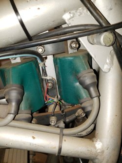
This is on a 180 with IIS ignition and Dyna 3 ohm dual output coils. The front coil has one coil output connected to ground at the bottom of the coil.View attachment 101678
Well as they say “every days a school day”I would never have thought you could do that.🤔
Very interesting and great information gained from this forum 👍 Thanks guys.
 
Back
Top