RGS not charging

I can see a problem. There are three wires that come from the three poles of the alternator, yellow, blue/white and green/white. There are duplicate yellow and blue/white wires, spliced on to the corresponding wire a little way up the loom, I don't know what they were ever for, possibly testing, but can be considered spares. So connect one of each colour, yellow, blue/white and green/white from the alternator to the rectumfryer and report back. We'll be here all week.

Smoke is generally considered to be a "Bad Sign", and hopefully you shut it down before anything awful happened.

Regarding the diagrams, there are some differences between the USA wiring and others, e.g. the alternator wiring diversion to the headlight switch. Apologies if that caused confusion earlier.
Not sure if your bike is originally built for the US or imported later. Also the “executive” alterations may have been done later. Sometimes you can get clues from the Laverdamania register, but at the end of the day, your bike has had previous owners, so anything could have happened...

Pic of my old rectifier below. You're using the correct colours, yellow, red-white and blue/white for the AC from the alternator. As mentioned, these can be in any order, and red and black are your DC side to the battery. Note on mine the deformed insulation on the red and black. This tells me that the DC wiring in this section is generally overloaded. If the wires are tied too tightly or pulled across a sharp edge then the copper pushes through the hot softened plastic and you've got a short circuit, which is unfused from the factory, so another source of Bad Signs. If you retain that old rectifier I'd suggest inspecting and sleeving the red (+) DC wire separately.

IMG_0527.jpeg
 
Last edited:
Thanks for the replies. I’ll see what I can do. Any ideas on the reversed wires in the fuse panel?

FWIW I took the rectifier out yesterday and it is a Nippon Denso so I am guessing that it is original to the bike.
 
After another look at all four diagrams for the RGS and RGA both the standard and the USA models they all showed that the two black wires should be to the right of the orange wire in the fuse panel so I made that switch.

I also did a continuity test and found that I have continuity between every combination of the stator wires. I also have continuity from the chassis to all of the stator wires.
I also tried an ohms test and my meter just fluctuated with no meaningful results. It appears I have bigger problems than I was hoping for.

Question: This bike was made in Italy. Are they all made in Italy and just modified for those shipped to the American market?
Does anyone know the difference? Are they just detuned to pass US emissions?

I guess I’m gonna pull out the stator and see what I’ve got. If I find that I can’t repair it would a replacement be the same for the U.S. or Euro version?

I already ordered the 530 rectifier. If it turns out I don’t need it I have a few Kawasakis that it would fit so I’ll just keep it in stock.

I’m gonna start the hunt for a stator and see what’s out there. Any recommendations are welcome.

This all started over a derelict snowmobile at an estate sale. I was looking at it and another guy walked over and we started talking about it. I had been thinking about finding one as a project but this wasn’t the one. Anyhow one thing led to another and he asked me if I was interested in helping him with the Laverda. It had sat for quite a few years until he took it to a shop. It ended up being there for two years with no significant progress made. I agreed to help him and in a few weeks it was in my shop. He wanted to get it up and running so that he could sell it due to health concerns.

About 35 years ago I helped a friend of mine put together a Guzzi Ambassador that was a rolling chassis and boxes full of parts.
He lives in San Francisco and I live in New Mexico. I knew he liked unusual bikes so sent him a pic of the Laverda. He immediately texted me back saying that he wanted it. One thing led to another and he sent the owner the money. The plan is for me to get the bike up to snuff and then he will drive out here and do some riding with me for a few days and then trailer it home.

I wish I had never sent him that pic. lol
Cosmetically this bike is in pretty nice shape and mechanically solid. Unfortunately the electrical gremlins on this bike are a bit out of my realm but I will somehow make it run and charge properly one way or another.

That’s the situation. Now it’s time to hunt down some parts.
 
I had the stator and the rectifier failed on my bikes in the last 30 years. Both failures are simple to find. If there is no outcome of the generator/ starter cables there is the failure, if there is some and no outcome of the rectifier, it is the rectifier. Both parts costs about 100€ or less, no big issue.
 
Don't discount the Redax alternator and ignition upgrade kits that Redax in Queensland, Aus, can provide. Many bikes out there are running with excellent reliability with Red's stuff installed.
 
It does seem to be charging but not nearly as well as it should. I’ve got a rectifier on the way so I might leave the stator in until I can try the new rectifier.
Unfortunately I am still not confident that everything else is wired correctly.
 
Don't discount the Redax alternator and ignition upgrade kits that Redax in Queensland, Aus, can provide. Many bikes out there are running with excellent reliability with Red's stuff installed.
I’ll look into that. I haven’t been having much luck finding a stator for this bike. I may end up calling Rick. He doesn’t have one for this bike listed but I have sent a couple of stators to him that he has repaired for me.
 
In a nutshell, what is the main problem you're trying to solve? If it's only poor charging, that isn't a biggie. Wiring and charging are both things that can be checked easily with a multimeter and wiring diagram.
 
The Redax kit included a more powerful alternator and EI and is for 180s, especially the early electrically underpowered ones. Your RGS should have a powerful enough Altinator. He has stand-alone EIs for your bike. Thats if it's all functioning correctly.
 
Don't discount the Redax alternator and ignition upgrade kits that Redax in Queensland, Aus, can provide. Many bikes out there are running with excellent reliability with Red's stuff installed.
System you are referring to Quentin is for the Series 1 triples, Magoo is working on an RGS

Magoo, on your RGS, Stator is Nippon Denso 3 Phase x 250 watts and is the same as used on many Kawasaki bikes as well as others, look for a Kawasaki 250 Ninja or similar around the 1990-2010 age range, very common, can also use their Regulators as well, they are a bolt on replacement
Is the same Stator that I use for the Series 1 ignition/Charging system upgrades that we make

On your wiring from the Stator, you have 5 wires at the end of the Insulation cover, if you stripped back the insulation you would find that there are 3 x yellow wires coming from the Stator but Laverda for some reason grafted two more wires on to two of the yellow wires

What you see is the Yellow and Blue/White wires go to the phase wires on the Regulator
The Green/White wire pisses off up to the left hand Switchblock and only comes into play when the Headlight is switched on, strange set up
That phase wire then returns back to the Regulator using a Red/White wire (is actually Green/Red from the Switch Block but joins to the Red/White at the connector block)

There is a connector block within the head stock area where that Green/White wire and also the Red/White wire passes through and the pins for those wires can often burn out
If you look at the connector block which is a faded white colour by now you can often see heat damage to the block itself, sure sign of overload

When I rewire an RGS/RGA etc I delete that set up and run all 3 phase wires direct to the Regulator, makes far more sense to me doing it that way

HTH
Red
 
System you are referring to Quentin is for the Series 1 triples, Magoo is working on an RGS

Magoo, on your RGS, Stator is Nippon Denso 3 Phase x 250 watts and is the same as used on many Kawasaki bikes as well as others, look for a Kawasaki 250 Ninja or similar around the 1990-2010 age range, very common, can also use their Regulators as well, they are a bolt on replacement
Is the same Stator that I use for the Series 1 ignition/Charging system upgrades that we make

On your wiring from the Stator, you have 5 wires at the end of the Insulation cover, if you stripped back the insulation you would find that there are 3 x yellow wires coming from the Stator but Laverda for some reason grafted two more wires on to two of the yellow wires

What you see is the Yellow and Blue/White wires go to the phase wires on the Regulator
The Green/White wire pisses off up to the left hand Switchblock and only comes into play when the Headlight is switched on, strange set up
That phase wire then returns back to the Regulator using a Red/White wire (is actually Green/Red from the Switch Block but joins to the Red/White at the connector block)

There is a connector block within the head stock area where that Green/White wire and also the Red/White wire passes through and the pins for those wires can often burn out
If you look at the connector block which is a faded white colour by now you can often see heat damage to the block itself, sure sign of overload

When I rewire an RGS/RGA etc I delete that set up and run all 3 phase wires direct to the Regulator, makes far more sense to me doing it that way

HTH
Red
Thanks! I’ll have a look at all of that tomorrow.

The lack of three yellow wires coming from the stator has been puzzling me. That and the and the discrepancies between the USA wiring diagram and the Euro version.
I appreciate the info on the stator wires.

The USA diagram had me running the green/white wire to the red/white from the stator which resulted in smoke.

So here is what I have coming from the rectifier except of course the red to the battery and the black to ground.
IMG_2888.jpeg

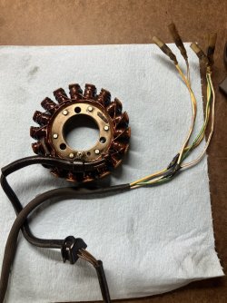
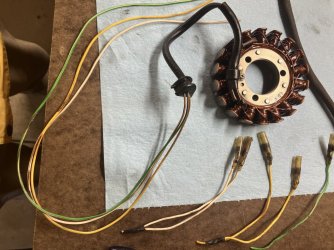
And here is what I have from the stator.
Two yellow, two blue/white, and the green/white. Which three wires should connect to the rectifier?
And I don’t have anything nearby to connect the green/white wire.
IMG_2889.jpeg

You’ll certainly be my hero if you can somehow pound into me how to wire this puzzle.

I also have looked before to try to find a connection for the green/white wire and the red/white with no luck. I looked at every block around the steering head and beyond. And none of the blocks show any sign of heat damage.

If I can get this thing wired correctly at the charging circuit I will eliminate the bullet connectors and solder the three wires to the rectifier for a more efficient connection.
 
Last edited:
looking at the condition of the insulators on the wires from the stator I would say
Left hand yellow is one of them as Insulator is fairly clean, it must be doubled up to one of either the two Blue/White wires
Same as the 2nd Yellow wire which must also be joined to a Blue/White

You can check that by checking for connectivity between the Yellow and Blue/White wires
Once you work out which wire is not doubled up you have solved the problem

So lets presume above is correct, you will have two sets of doubled up wires, either of the two can go to the Regulator
I would use the Yellow from one set and the White/Blue from the other set and join them to the Yellow and the White/Blue from the Regulator

Now you have the Green/White left, it is probably the one that is not doubled up so connect it to the Red/White

But above is just a guess, you really need to work out which wires are doubled up inside the Sheath
Again looking at the condition of the Insulators I would say left hand Yellow, the Green/White beside it and the far right White/Blue
At a guess

Looks like last owners have wired it so all 3 phases go direct to the Regulator which is good
Can tell wiring has been messed with as they installed an Ignitech, pity they only had one roll of Blue wire
Had a triple arrive here a few years ago and when I lifted the body work 85% of the wiring was red, FFS
 
On my RGS....the same colored wires from the stator were doubles. So one of each color is used to plug into the RR....anyone to anyone.
Did you test the alternator as I suggested awhile back? Voltage test. 75v AC BETWEEN the each of the 3 wires of different colors and each other (ignore the same colored ones which should be redundant, at least on my bike) at 3000 rpm or so.
 
After multiple fails I went ahead and ordered a reg/rec and a stator. They should be here soon so went ahead and took out the old stator. I was hoping to find the smoking gun but the stator itself actually doesn’t show any sign of getting hot.
IMG_2898.jpeg
So then I decided to clip the wires and pull the sheath off to see what I have.
IMG_2899.jpeg
And of course I verified that it doesn’t have any shorts in the wires. It is down to blue/white, yellow, and green/white.

I had been told that the green/white should go to the red/white from the rectifier but that always creates smoke.

I assume that my new stator will have three yellow wires and if I understand correctly I should be able to connect the wires from the stator to any combination of the three wires that connect to the stator. Is that correct? I’m still also concerned that there may be other issues caused by the previous owner.
 
Sad to see that you have been getting into a bit of a tangle with this wiring fsult.
Yes, any yellow alternator stator wire to any of the corresponding reg/rect wires.
ND alternator is pretty bullet proof as you have discovered. A 40 year old reg/rect less so and well worth changing for peace of mind even if it tests OK.
It would be worth checking whether one of the alternator outputs is running through the LH handlebar switch as originally configured . Many of us have suffered problems with overheated/burnt connections.. and in one case the soldered switch wire melted the solder and created a short to the handlebar. Either of these may explain your smoke!
As has been explained, this arrangement was to avoid overloading the reg/rect. Assuming your new item is sufficiently well rated to cope with the 210w alternator output then it should be bypassed. Green/white runs to the handlebar, red/white is the return.
Do carefully check the 9 way plug under the tank which carries the switched alternator phase. The nylon block is likely brown / melted on one corner due to high resistance across the connector pins.
Similarly your alternator bullet connectors / sheaths look to be discoloured and again this signifies high resistance. Replace the connectors.
 
Last edited:
Thanks for the reply. I do not have a green/white wire ran to the left hand switch.
That probably explains why when I plug it into the red/white wire I get smoke.
I’m sick of working on this bike so today I did some work on my 1972 CB500 four project. It was great to actually get some progress from my labor. lol

I did get the parts for the Laverda today so I’ll get back on it in a day or two. Meanwhile I’m gonna have beer or two while I work on the CB.

Cheers!
 
...lot to read, if not already noted. Most of the original bullet connectors have overheated, particular the 3+2 from the stator. These take the shunt current from the generic ND, and the more robust Shindengen preferred upgrade shunt or series type RR. This shunt current exceeds 25A at zero volts, short circuit. While 25A bullet connectors ( usually yellow ) will last a certain time, the rating is exceeded in operation. Tunnel connectors would mitigate this overheating issue. HTH j
 
Back
Top