Techy Stuff and Why

julian

Hero member
Location
Belgium
This thread is intended for people to post up what they are doing, Engine mods, chassis mods, special repairs etc that others may find interesting, no one needs to be an expert as there are no experts in the world in my opinion, just those that think they are. Everyone can learn from each other and that is what this thread is about. Showing what you are doing, asking questions, listening to comments and telling why you do it like this or that and finding improvements to ideas.
Hopefully this will become a nice source of info for us all in the future.
 
I'll start it off.

Laverda 750 Combustion re-shaping.

As standard the SF head has a pretty poor combustion chamber shape for very high levels of power, It flows fairly well but in order to get a good compression ratio you need to have a large dome on the piston, thus causing obstructions to the flame travel and slowing the combustion down to an extent that you need large amounts of ignition advance and therefore loose power and bring on the likelihood of detonation occurring.
You also have a large combustion chamber surface are that causes heat problems. All bad things.

Solution.
Close up the combustion chamber to make it as small as possible without obstructing inlet and exhaust flow,
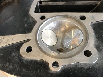
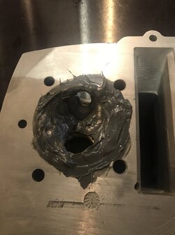
First I did some experiments by raising the valve seat into the combustion chamber and found that flow would go up the longer I made the straight "behind seat area" so then filled in the rest of the chamber with epoxy (this is just for experiment)

Problem, Then found that although better in shape it was unworkable as the valves would hit at about 4mm lift on overlap and I was intending to have a lot more. (Full race engine)

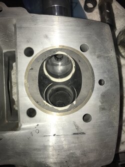
Solution, change the valve included angle to move the heads of the valves apart and to allow an even longer "short side" to the inlet and exhaust port, Flow went up again and valves would not hit each other even at full lift. (look at the space between valve seats in the pics)
This also meant that the combustion chamber was now 11mm shallower than before so even less combustion chamber surface area and more squish surface area. Meaning I could run a higher compression ratio with only a very minimal 3mm high dome on my 88mm diameter piston.

In the end I have a CR of 13.5:1 with a 2.88 mm domed piston and 9mm deep pockets for 43 and 36 mm valves


The rest of the head mods to follow in another post.


PS,
Don't test on the flow bench with Plasticine, flow benches eat it :D
 

Attachments

  • IMG_5223.JPG
    IMG_5223.JPG
    154.7 KB · Views: 66
  • DSCN1209.JPG
    DSCN1209.JPG
    100.9 KB · Views: 66
  • IMG_3016.JPG
    IMG_3016.JPG
    99.2 KB · Views: 67
  • IMG_3036 (2).JPG
    IMG_3036 (2).JPG
    160.9 KB · Views: 67
  • IMG_5216.JPG
    IMG_5216.JPG
    155.3 KB · Views: 67
  • IMG_7794.jpg
    IMG_7794.jpg
    182.7 KB · Views: 66
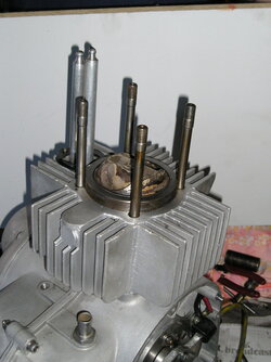
I was looking after and developing several Aermacchi's locally a few years back. They've pretty much all stopped now as the cases are getting old and from this end of the world replacements are hard to source. They were all road bike based engines so had the very deep hemi combustion chambers which are stock on this model. The genuine race models have a shallower chamber.
Being stuck with this chamber - and the subsequent large amounts of ignition advance required - we set about seeing what we could do about it. Using a welded Suzuki GS500 piston - same bore and pin size - we tried a couple of different crown shapes. The pic is what we ended up with - it matches the chamber shape closely then has a flat top. Even with the big valve cutaways it's a much more compact chamber. Advance came down to 28 degrees. Compression 12.8 :1
The valve seats are cut back a little. Mainly to get valve to valve clearance at overlap. Inlet lift is .460in, Exhaust .440in
Once the shape was sorted, we went through a local agent and had Ross forgings machined to the pattern.

This was the cheaper alternative to welding and remachining the chambers. For our purposes it worked. I have some experience with the bathtub shape chambers Julian has arrived at. Yes, the squish is nice - but I've found that the chamber walls interfere with flow from the inlet at part lift. You finish up with the inlet sitting in a radiused pocket at one end of the bathtub. I'll be interested to see what advance this chamber requires.
 

Attachments

  • p7010014.jpg
    p7010014.jpg
    130 KB · Views: 45
Hi Greg,
I kept the area at the side of the valve at low lift to 38% of lift minimum, the recommended is 30% and found that at all lifts it made no difference after 31% on my engine, even with no material at all added it did not flow any more, in fact in the final shape I actually picked up about 10cfm by adding the material you see in the last pic. Very interesting stuff airflow and never the same from one engine type to another. This was all tested with the cylinder bolted to the head to make sure it was a "real" test.

Your Aermachi is very interesting and reminiscent of an issue we had with the old 6 cylinder Riley engines we used to run on Methanol. 13.5:1 CR and massive domes on the pistons, (actually Triumph 650 race pistons) we went down to 10.5:1 and a very slight dome and picked up 15hp at the top with equivalent power gains right through the rev range, as you say, less advance also so less parasitic losses. 160hp @ 6000 rpm from a 6 cylinder 2 litre pre-war 3 bearing crank, long stroke N/A engine with very small ports. More development would have no doubt given us more but we then supercharged.

Regards,
J
 
wish we lived closer to each other Julian, be interesting nights around the workbench after work just swapping ideas
you are really pushing the envelope with the 750

We spent days on the Flowbench working out what works on a standard triple cylinder head which is way flawed in its design
Was probably considered not so bad back in the day when it was designed but is difficult to get to flow big numbers
Spent nearly 3 full days welding up and reshaping the Inlet and Exhaust ports to get the ports to flow, reduced Exhaust valves to 33mm in the end and changed the shape of the bowls/throats and D Shaped the Exhaust ports using the D as the floor to give us some exhaust port flange reflection

Inlets went out to 42mm and even with those numbers we know we are not close to being close to the theoretical correct numbers
But is working and we are generally in front of our competitors so is okay for us at the moment
Getting the bottom end to survive with 135hp rear wheel is the main restraint at the moment, been a big learning curve
 
wish we lived closer to each other Julian, be interesting nights around the workbench after work just swapping ideas
you are really pushing the envelope with the 750

We spent days on the Flowbench working out what works on a standard triple cylinder head which is way flawed in its design
Was probably considered not so bad back in the day when it was designed but is difficult to get to flow big numbers
Spent nearly 3 full days welding up and reshaping the Inlet and Exhaust ports to get the ports to flow, reduced Exhaust valves to 33mm in the end and changed the shape of the bowls/throats and D Shaped the Exhaust ports using the D as the floor to give us some exhaust port flange reflection

Inlets went out to 42mm and even with those numbers we know we are not close to being close to the theoretical correct numbers
But is working and we are generally in front of our competitors so is okay for us at the moment
Getting the bottom end to survive with 135hp rear wheel is the main restraint at the moment, been a big learning curve
Red, what is the weak spot in the triple bottom end? Is there not enough support in the cases? When I did Kawasaki engines back in the 90"s we put over 500HP through Kaw cranks and cases on a 1500 cc pro mod drag bike, our problem back then were transmissions.
 
Red, what is the weak spot in the triple bottom end? Is there not enough support in the cases? When I did Kawasaki engines back in the 90"s we put over 500HP through Kaw cranks and cases on a 1500 cc pro mod drag bike, our problem back then were transmissions.
I'm sure Red will give us his views but I've built both Z's and a hot triple. The kawasaki cases are a concrete bunker compared to the brick cottage of the Laverda. Crank is better supported in the Z - and with a shorter stroke it's stiffer too..
 
I once got a look inside the GT bevel cases that Gowanlocks built and raced, talk about a web of welds Everywhere. I don't know if it was crack repair or reinforcing but so much TIG.
 
I once got a look inside the GT bevel cases that Gowanlocks built and raced, talk about a web of welds Everywhere. I don't know if it was crack repair or reinforcing but so much TIG.
Probably both. Bevel Ducs crack the cases quite easily so it's a question of weld before it cracks - or after. I built a 450 for a local guy which made very good HP on methanol. But we finished up with both his sets of cases cracked around the timing side main. They went to the guy who did Gowanlochs bottom end work. 3 years later we got them back. Very nice job though, lol.
 
I'm sure Red will give us his views but I've built both Z's and a hot triple. The kawasaki cases are a concrete bunker compared to the brick cottage of the Laverda. Crank is better supported in the Z - and with a shorter stroke it's stiffer too..
correct, too much engine case flex going on, in the end we custom machined 10mm x 1.25 lower engine studs so we could increase the clamping forces, changed to machined brass cage crank bearings and pinned the bearings to the cases
since then not had any more crankshaft issues

standard 8mm studs on the left, our 10mm studs on the right machined from 4130, we also machined up all the 6mm studs from Titanium

custom engine studs
 
I find all this very interesting. Maybe an addition to the thread or even a separate one could focus on repairs done by the side of the road to keep the show on the road.
 
Hi Red, yes I would love to come over in the evening and steal all of your secrets, thank you very much :D:D:D
You are lucky, 12000 miles is probably far enough ;) But we could have some nice ideas together.

I am really hoping that due to the narrower engine than the triple and the short stroke coupled with the very stiff one piece crank and plain bearings that we will get away with it for the time being. I have been watching Red's progress and already have uprated super strength crank studs and head studs in MP35P maybe I will have to go up in size but hoping not needed.
Also due to the very short stroke and high revs in theory the crank load will be less than in Red's triple but only time will tell.
I am also hoping that the plain bearings will impart a much more gentle load on the crankcase than the rollers. (in theory)
Going to be some long nites ahead.

Best regards,
Jules
 
Julian,

The '73 SFC works motors had 12mm head/barrel studs. Not sure if it really was necessary, obviously the factory thought it was.

piet
DSCN7343.JPG
 
Hi Piet,
I have head studs in MP35P also, these would be far stronger than 12mm in the same material as the std studs, I don't know what the std studs were made of but a mate of mine put them under the strain gauge and they went off before a basic 8.8 so it would not have been a bad move by the factory.

I am also going to use HT nuts and washers on all the studs as this makes an incredible amount of difference to the clamping load possible,
With aluminium cases the washers were found to be the most important as even "if" you could get the correct torque with a softer nut and washer the load went "into" the ally case and not "Through it" so the clamping load although torqued the same was considerably less on the joint. Its really amazing what you find when you start actually measuring stuff.
We found this out trying to fix a constant head gasket problem with a pre-war designed race engine with a mass of very small studs and low torque. We had already gone to top quality studs, upped the torque, and a top quality gasket and still got gasket issues constantly, changed to HT flanged nuts and it was better but not gone. Then did the research and tests, changed to HT washers and the problem was completely eradicated. Amazing.

Jules
 
Lots of times pulling my head required so much banging with the soft hammer. Now fixed hopefully with hardened washers as big as possible, without them the head would collapse and pinch slightly around the studs.
 
Exactly Vince, we would even find the same thing happening with cast iron. Quite amazing the extra clampin after fitting hard washers, let alone better studs and nuts.
J
 
Back
Top