wanted - moto giro bike

Any idea how many splines?
Knowing that, you can work out how many degrees a move of one spline entails.

Paul
Hi Paul

as I did not understand the significance of the fine splines, I did not count them. When you take the 175 engine apart, when you lift the crank out of the case you will see exactly what I am poorly trying to explain. There is a long thin rod with thin splines on each end that is inside the hollow of the crank end and connects the crank to the lower gear assembly. Not a very substantial rod at all.

I bet the 175 and 150 are identical. If you get deep enough into the 175 engine that you pull the crank, would you mind counting the fine splines on each end of the rod and reporting back? Thanks. I am not overly keen to split the cases yet again just to count splines..
 
That's called a quill shaft. It's usual function is to twist and absorb shocks in a drive line. It's definitely unusual to see one in the primary drive.
Incidentally, even if it is a very fine spline, because it's on the crank end of the gearing, one spline will still be quite a lot at the cam.
 
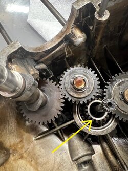
Is this the spline you're talking about Paul? (yellow arrow in the photo below)

I noticed it when I first started looking at your valve timing issue. I thought it might have potential as a Vernier* type adjustment, but only if it had a different number of splines than the number of teeth on the crank timing gear. But it appears to have 17 splines, same number as teeth on the gear, so it doesn't offer any potential for finer adjustment than simply moving a tooth either way on the gear.

Sorry if I've just burst a thought bubble.

I actually didn't count the teeth on the crank timing gear because it's not in the photo. I counted the teeth on the cam gear and divided by 2. I may have mis-counted the hidden part of the spline or gear, so I'd suggest you re-confirm the numbers yourself. Count the splines on the crank and teeth on the crank gear. If they are different numbers, then you do indeed have a vernier type adjustment.

I also could have mis-identified components in the photo. I assumed the thing identified with the yellow arrow was a spline rather than the timing gear itself because the teeth look the wrong size to engage with the intermediate timing gear. But it it is indeed the gear and it has a fine internal spline, then yes. You are absolutely correct.

*By Vernier, I mean that you can go forward one step on the spline and back one tooth on the gear (or vice versa) to change the timing by the difference between them.
 

Attachments

  • crank spline.jpg
    crank spline.jpg
    132.9 KB · Views: 29
Last edited:
Is this the spline you're talking about Paul? (yellow arrow in the photo below)

I noticed it when I first started looking at your valve timing issue. I thought it might have potential as a Vernier* type adjustment, but only if it had a different number of splines than the number of teeth on the crank timing gear. But it appears to have 17 splines, same number as teeth on the gear, so it doesn't offer any potential for finer adjustment than simply moving a tooth either way on the gear.

Sorry if I've just burst a thought bubble.

I actually didn't count the teeth on the crank timing gear because it's not in the photo. I counted the teeth on the cam gear and divided by 2. I may have mis-counted the hidden part of the spline or gear, so I'd suggest you re-confirm the numbers yourself. Count the splines on the crank and teeth on the crank gear. If they are different numbers, then you do indeed have a vernier type adjustment.

I also could have mis-identified components in the photo. I assumed the thing identified with the yellow arrow was a spline rather than the timing gear itself because the teeth look the wrong size to engage with the intermediate timing gear. But it it is indeed the gear and it has a fine internal spline, then yes. You are absolutely correct.

*By Vernier, I mean that you can go forward one step on the spline and back one tooth on the gear (or vice versa) to change the timing by the difference between them.
Hi Cam

yes, I am referring to the long skinny rod sticking up from the center of the hole, has splines on either end. I have come to the conclusion that for the couple of degrees my engines cam timing timing is "off", worst case is it should give a little more power/torque in the mid range, no bad thing, so I am going to resist the urge to split the cases again. Paul Marx may be able to shed some more light on this once he and Ariel pull the Gilera 175 engine apart.

Thanks again for all the help!!!
 
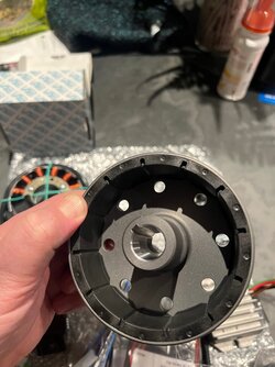
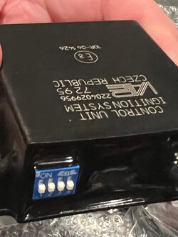
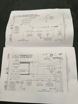
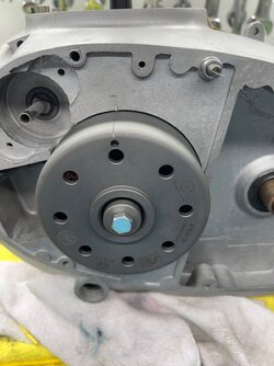
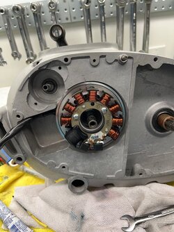
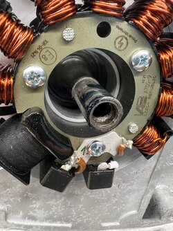
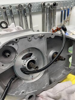
the VAPE (PowerDynamo) 12 volt charging system conversion with digital ignition has arrived. The instructions for timing are messing with my head again. Just says to set piston to TDC to time by lining up timing marks, doesn't say anything about which stroke. Guessing it may just fire each crank rotation with a waste spark like a Harley ignition? Also does not give any information about changing timing settings with the four switches or what the ignition "curve" base timing is, going to email VAPE and ask.

electrickery has never been my thing at all. The basic mechanics of installing and static timing the VAPE system looks easy, but the bike came to me without brake light wiring or brake switching, no kill switch, no turn signals, burnt up ignition wiring, a mangled ignition switch without a key, and a butchered wiring harness. Just going to start from scratch, easier for some than for me, but I will persever.......

Still waiting on the painter for my frame and everything else, so will just install the VAPE bits on the crank end and line up timing marks for now, and get on to making an enormous mess polishing the wheel hubs etc.....:eek::eek::eek::eek::rolleyes: Going to set the polishing equipment up outside in the driveway this weekend if weather permits.
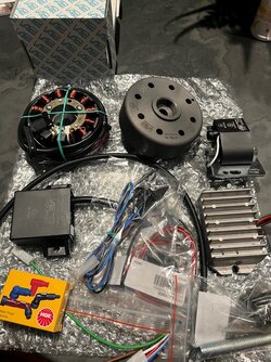
 

Attachments

  • Vape 1.jpg
    Vape 1.jpg
    233 KB · Views: 17
  • Vape 2.jpg
    Vape 2.jpg
    122.3 KB · Views: 17
  • Vape 3.jpg
    Vape 3.jpg
    97 KB · Views: 16
  • Vape 4.jpg
    Vape 4.jpg
    109.7 KB · Views: 17
Hi Cam

yes, I am referring to the long skinny rod sticking up from the center of the hole, has splines on either end.
OK. It's not clear to me how that skinny shaft affects the cam timing. But if it does engage with the timing gear then you have roughly 5° crankshaft increments in valve timing.

The gear has 17 teeth. 360°/17 = 21.17°
The spline has 22 teeth. 360°/22 = 16.36°

So going forward on one and back on the other will shift the crank by the difference between the two increments, which is 4.81°

I've used a similar method to dial in Bevel Ducati valve timing, except that they have 3 pairs of meshing gears in the valve train with different numbers of teeth, so there's a finer adjustment of about 2° available.
 
Hi Cam

yes, I am referring to the long skinny rod sticking up from the center of the hole, has splines on either end. I have come to the conclusion that for the couple of degrees my engines cam timing timing is "off", worst case is it should give a little more power/torque in the mid range, no bad thing, so I am going to resist the urge to split the cases again. Paul Marx may be able to shed some more light on this once he and Ariel pull the Gilera 175 engine apart.

Thanks again for all the help!!!
We'll try to remember if we go that far. The top needs to be pulled because the cylinder needs painting.
I should imagine that 125, 150, 175 are identical.

Paul
 
OK. It's not clear to me how that skinny shaft affects the cam timing. But if it does engage with the timing gear then you have roughly 5° crankshaft increments in valve timing.

The gear has 17 teeth. 360°/17 = 21.17°
The spline has 22 teeth. 360°/22 = 16.36°

So going forward on one and back on the other will shift the crank by the difference between the two increments, which is 4.81°

I've used a similar method to dial in Bevel Ducati valve timing, except that they have 3 pairs of meshing gears in the valve train with different numbers of teeth, so there's a finer adjustment of about 2° available.
thanks Cam. I know I am not describing it well. so far as I can determine hat small splined shaft is what orients the connection of the crank to the gears that drive the cam. However, I am not splitting the engine cases again just to try to change cam timing a couple of degrees. Moving on to polishing things now, then wheel building.
 
timed to TDC, took a bit of fettling to get a nice fit
 

Attachments

  • conversion 4.jpg
    conversion 4.jpg
    114.3 KB · Views: 26
  • conversion 3.jpg
    conversion 3.jpg
    169.2 KB · Views: 24
  • conversion 2.jpg
    conversion 2.jpg
    195 KB · Views: 25
  • conversion 1.jpg
    conversion 1.jpg
    147.6 KB · Views: 25
Neat. Looks like it has 2 pickups and a generator coil. I wonder why it has two pickups. Handy that the ignition is on the crankshaft. You don't have to muck about making sure it's on the compression stroke.

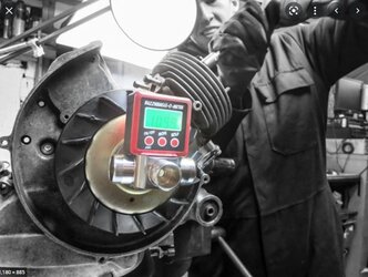
If you don't want to mess about with a timing disk for static timing, a digital inclinometer will do the same job. They sell from around $20 to $50 in hardware stores. It'll give a digital readout from 0 to 360°. Most of them have a magnetic base (not a magnetic back) so you may need to make an angle bracket to fit it to your crankshaft rotor. Lambretta guys have been doing it that way for years and they've made a special 4-way threaded adaptor that screws into various rotor threads. You can buy it as a kit including the inclinometer that they call a "Buzzwangle". I dunno if any of the Lambretta threads on the adaptor are relevant to anything else though. Obviously no use for dynamic timing with a strobe!
 

Attachments

  • buzzwangle.JPG
    buzzwangle.JPG
    65.1 KB · Views: 27
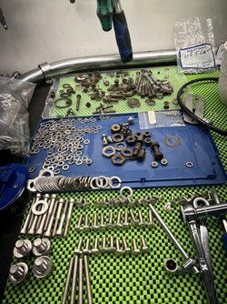
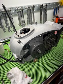
engine case now fully closed up, all new stainless steel case fasteners sealed with copper crush washers. Been tapping and chasing threads to ensure everything goes back together smoothly. Had to retap two of the cylinder stud holes, all four cylinder studs now seated properly.

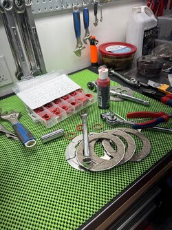
Dry clutch, which had not sunk in at first. I caught myself about to soak the fiber clutch plates in engine oil, then stopped, leaving the clutch fiber plates dry. The nut that holds the clutch basket to the output shaft is buggered. The threads on the output shaft cleaned up OK but the nut is beyond saving, stopped for the evening to try and source a new output shaft nut tomorrow.

Roughly minus 20 Celsius and snowing heavily, so too cold and miserable to set my metal polishing rig up outside, and the polishing process is just too messy to do inside my relatively clean(ish) garage, so waiting on better weather for polishing wheel hubs, clutch cover, etc..
 

Attachments

  • assemble 8.jpg
    assemble 8.jpg
    226.4 KB · Views: 30
  • assemble 7.jpg
    assemble 7.jpg
    210.5 KB · Views: 30
  • assemble 6.jpg
    assemble 6.jpg
    251.7 KB · Views: 30
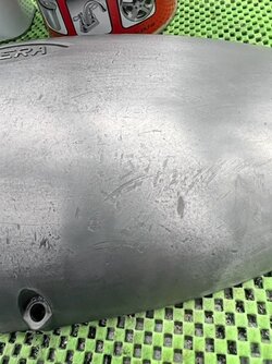
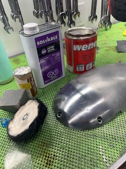
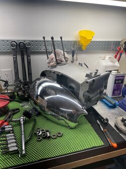
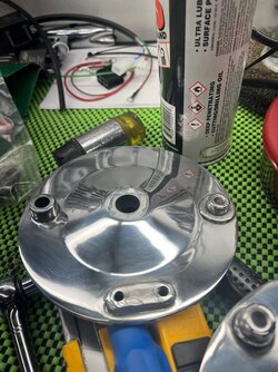
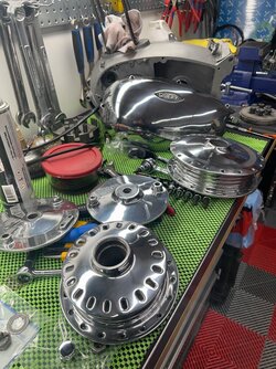
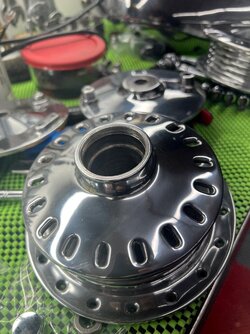
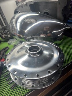
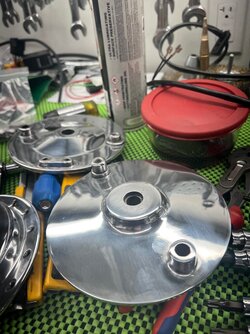
polishing is complete. Most of the work, like in painting, is in preparation. In this case, cleaning by ultrasonic, then vapour blasting, then power sanding, then hand sanding, then bead blasting. After all of that, the surface was mostly free of 65 years of dents, dings, scratches, and major blemishes. Only then did the polisher get fired up. See photos.
 

Attachments

  • polish 3.jpg
    polish 3.jpg
    98.6 KB · Views: 25
  • polish 1.jpg
    polish 1.jpg
    114.5 KB · Views: 24
  • polish 9.jpg
    polish 9.jpg
    180.6 KB · Views: 25
  • polish 8.jpg
    polish 8.jpg
    165.1 KB · Views: 24
more shiny.

now to fit the new wheel bearings, and spoke and true and balance the wheels. New custom made polished stainless steel spokes from Central Wheel in the UK, new Raedelli Aimon Sport chrome rims from Italy.

My fancy new high quality beautifully machined wheel balancer just arrived earlier today from Marc Parne http://www.marcparnes.com/ complete with all the different cones needed to do everything from my supercharged H2, my Harley, the various LAverda triple wheels, the Gilera wheels, and pretty much any other motorycle wheel. I will post a review after I use the new balancer on the Gilera wheels. I am still replacing garage tools destroyed in the garage fire November 2020, this new wheel balancer is a definite upgrade over what I had before.
 

Attachments

  • polish 4.jpg
    polish 4.jpg
    219.9 KB · Views: 29
  • polish 5.jpg
    polish 5.jpg
    147.8 KB · Views: 27
  • polish 6.jpg
    polish 6.jpg
    133.2 KB · Views: 28
  • polish 7.jpg
    polish 7.jpg
    149.4 KB · Views: 29
now at the 8 week mark since the frame and everything else dropped off with the painter. Terms and promise was completion is "6 to 8 weeks". Politely followed up with the Croatian speaking painter who now promises (through his English speaking wife "that if all goes well" another week or so. No idea what that means, other than I don't have my painted parts to begin assembly...... I hate relying on anyone, this better be a spectacular paint job;)

on the weekend I used a Quartz Ceramic metal clear coating on all the polished bits to see if it will preserve the shine. We'll see.

I also spent a couple of hours assembling the hubs and sprocket carriers with new bearings and spacers. All the bearings have pin drive screw in bearing retainers, a lot of fine detail for such a little bike. Bit of an ooops. Got teh hubs and sprocket carrier asembled, cleaned up, and found a remaining steel spacer in my dwindling pile of original bits. Was franctically leafing through parts diagrams trying to figure what I left out. Walked away ,scratched my head, then ultimately happily realized the "spacer" was actually the old piston/rod pin surplus to requirements....... Bloody hell

Started fitting the old brake shoes, first time I really looked at them, lots of thickness but heavily glazed and clearly not contacting the drum very well. The Gilera parts suppliers tell me the shoes are no longer available and suggested I get them stripped and relined, the arced to the drum. Did a quick Google search, not coming up with anyone near me that performs that service. Lots listed in the UK, Australia, and a few in USA. Not sure what I am going to do about brake shoes, assuming if these area as old as they look probably asbestos and a safety hazard.
 
Started fitting the old brake shoes, first time I really looked at them, lots of thickness but heavily glazed and clearly not contacting the drum very well. The Gilera parts suppliers tell me the shoes are no longer available and suggested I get them stripped and relined, the arced to the drum. Did a quick Google search, not coming up with anyone near me that performs that service. Lots listed in the UK, Australia, and a few in USA. Not sure what I am going to do about brake shoes, assuming if these area as old as they look probably asbestos and a safety hazard.
You should be able to check the drum for ovality easily enough and if there's plenty of meat on the shoes, skim them in a lathe. If the problem persists, you'll need new shoes.

Paul
 
Back
Top