Building my Jota

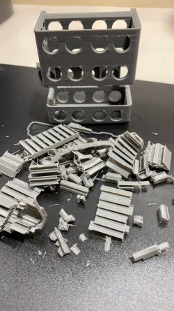
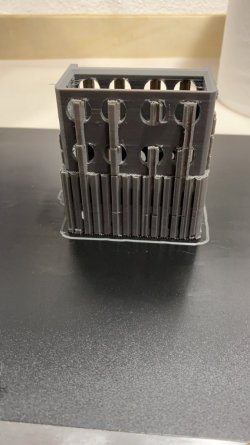
A bunch of electrics photos today. I printed the final ignition box holder today. This first photo is how it prints with the supports which allow me to print over hangs , which are the tops of the lightening holes. I could have printed it with 20% infill, semi hollow, but I chose to go 100% infill with lightening holes. It made it stronger, lighter and I liked the aesthetics of it. This was a 23 hour print. And 45 minutes on cad.
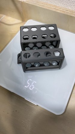
The next photo is after the supports are pulled off, then on the scales without a clean up, it comes out at 56 grams. It needs a sand on the edges to make it a bit tidier. I’m printing a rubber cushion that the ignition box sits on inside as will for a bit of dampening. The bulk head everything mounts to is also rubber mounted.
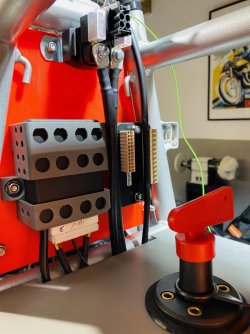
I think it looks like it’s meant to be , where it’s mounted. I made a huge leap in the wiring today. Most cables have at least one end crimped , I will crimp the other ends at work Monday , by a massive Strack of good fortune, and with no skill involved they all just fall into place and look tidy .... beginners luck.
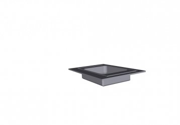
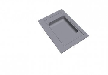
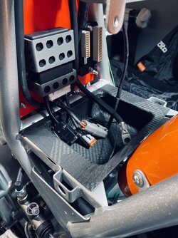
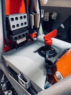
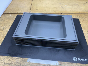
The last two pictures are the tray that sits under the kill switch ( old battery tray floor area). This will be filled with all the connector plugs for the ignition box , regulator and the kill switch connections. The box in the pictures is my rendering. It’s printing now, it will be done at 2300 tomorrow Sunday night. It’s a 33 hour print. And 30 minutes drawing on Cad. This print gets used as a female mould for a carbon lay up. I wanted a really strong light tray that wouldn’t crack or warp like plastic would. The recess line around the lip of the tray is the actual size of the tray , the recess marks out perfect edges when we vac bag the carbon down , so we get a nicer cut, past the recess is just extra flat area for lay up. Hopefully I will be done with this Thursday, and installing the tray/ box on Friday .
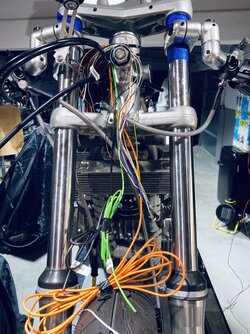
the single small green wire is only one of two wires for the dash lights, and control switches that runs forward , the other will be an earth , so it keeps the switch gear loom minuscule. The M button up front by the clip ons takes care of the rest.
I decided to not run the m button in the clip ons. The wiring will still be in the clip ons , but the M button will be in a small sealed thick walled Ali tube mounted on a bracket by the steering head.
D9940249-D6C9-440B-B703-998EEF80B20A.jpeg
 

Attachments

  • 58BC6658-E947-4F58-8D84-50FCE9704DE8.jpeg
    58BC6658-E947-4F58-8D84-50FCE9704DE8.jpeg
    128.8 KB · Views: 66
  • 8A6DD800-3353-457B-9AE8-52FC9143A0CD.jpeg
    8A6DD800-3353-457B-9AE8-52FC9143A0CD.jpeg
    67.3 KB · Views: 80
  • 8AF69A3C-ABA3-4F52-9D5C-1AAC8DAB2EFD.jpeg
    8AF69A3C-ABA3-4F52-9D5C-1AAC8DAB2EFD.jpeg
    139.2 KB · Views: 72
  • FF2EAFAD-8757-42CD-AF0B-245379F04435.jpeg
    FF2EAFAD-8757-42CD-AF0B-245379F04435.jpeg
    18.3 KB · Views: 72
  • 1092D33D-4938-42C5-A2EA-6CD9A9279189.jpeg
    1092D33D-4938-42C5-A2EA-6CD9A9279189.jpeg
    23 KB · Views: 66
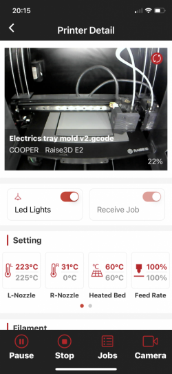
Here’s a view of what I can see at home from monitoring the printer at work . I have a live feed over the cloud. So I can see it printing, it’s a poor camera feed, it has to be said , but it shows what I need to see. The data below it shows I have turned on the LED lights. The left print head is running 223 degrees and that the heat bed is at 60 degrees. So all is as it should be , it’s 22% printed. It’s an amazing tool.


C187F895-69B0-4C7D-9EA3-A766F199A787.png
 
It started with Mecharno Sets, look at me now. Talk about Computer-Aided Design. And Julian using his Optuma Race Engine Computer gadget. Where is my Hammer, I feel like a Dinosause watching the future arrive
 
More dry fitting today. The carbon tray needs a little trim on the front lip and some entry holes in the front wall of it. But you get the idea of how it works. Keeps things today and clean. The third photo is the mould I printed for it. Worked a treat. Working on the moto gadget wiring today. And trying to find somewhere hidden yet sensible to put the horn !
 

Attachments

  • 0834FEAC-D923-441E-9113-A149EDC42415.jpeg
    0834FEAC-D923-441E-9113-A149EDC42415.jpeg
    174.2 KB · Views: 93
  • D0C57E43-539C-4E51-AF0D-9A82B41702CA.jpeg
    D0C57E43-539C-4E51-AF0D-9A82B41702CA.jpeg
    144.7 KB · Views: 93
  • 57CCDE94-60CC-43AF-8BAD-815A1E85DC1A.jpeg
    57CCDE94-60CC-43AF-8BAD-815A1E85DC1A.jpeg
    178 KB · Views: 102
Todd... don't forget about starting that engine.... or one night while you are sleeping you will hear it suddently. It will be me after finishing my waiting patience:D:p


Soon brother , soon, I just had an update on my exhaust, so I am hoping that will be finished next week.....
I took a night off the shed last night, My Mother is about to leave to head back to NZ after being with us for the last 6 months, sounds like a long time, but time flies, and then in the last few days it just doesn't seem to exist, so there is lots of family dinners going on and good memories being talked about at the moment.

Ha ha, that's what I thought either ...
😇
 
Hey Todd, are you on a go slow with your project? I’m missing the updates, keep em coming.
Hi Mate

feels go slow ! last week one of my nippers broke her shoulder horse riding , which threw the house into disaster mode. Mum stayed at the hospital, and I ran work and home at the same time. Each morning 160km round trip for school runs and the same in the afternoon. Then kids at work with me till 1800 , Then home and dinner and homework. Everything is stabilised now. Back on the tools today !
 
Hi Rob

she’s out in the breeze. AMD on the front side of the bulkhead. Anything that doesn’t need to be hidden, water proofed or cooked by air gets hidden on the other side. This red bulkhead will later be in carbon painted satin black. It’s just my template, kind of like the old bread board electronic kits kids had when they were young .... if anyone remembers those ... I’m younger than most so the ones from Dick Smith ( aussies and kiwis will know this brand) came on particle board! The guys that built the reg said it’s fine on its side and could be hidden away as well but this gives me some extra space by it being out here. This one is custom made for lithium batteries , which sounds posh but in all reality it’s only 20 euros more than an off the shelf item , and I know it’s not a Knock off or a fake as it was made for me. So it was worth to pay the extra 20.

View attachment 54906
Hi Todd, I have been enjoying your blog a lot as much is relevant to my current rebuild. Is this the Ricks Motorsport Electrics regulator you mentioned in earlier post? Could you give me their part number so I may order one?
 
Hi Todd, I have been enjoying your blog a lot as much is relevant to my current rebuild. Is this the Ricks Motorsport Electrics regulator you mentioned in earlier post? Could you give me their part number so I may order one?
Hi Mate. Yes it is. They have been great to work with on this. If you mail Mike C on this mail MikeC@ricksmotorsportelectrics.com
Tell him Todd from Mallorca sent you and he will sort you out. They are top blokes.
 
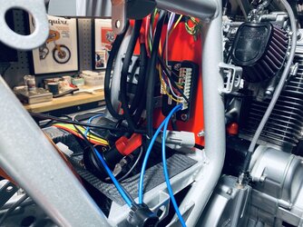
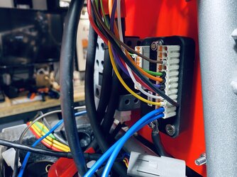
So a big wiring day today. Well at least for me. When you aren’t familiar with what you are doing , it takes more time , but with music and espresso in the shed, I don’t care how long it takes ....it’s good for the soul.
I have now run all the wires , I just can’t bring myself to scrape earth points on my nice fresh frame.... I know I have too, but a few more days of no scraping will be ok. I know I harp on about the motogadget system, but it really is good, especially if you buy a wiring kit for the loom, it comes with more than enough wire to wire the whole bike , with colour codes for each item, and pin crimps so the the wires anchor securely in the m unit. It takes a lot of guess work out of it , and gives you some confidence. This week I will do the frame earths, and power the system up, and then run all the wiring through cable conduit , once I see everything is working correctly.
it is actually a really nice job crimping and getting everything hooked up , made even nicer with the right tools , and as I have 3 more laverda to build as my projects, I have invested in getting the right gear to do all the jobs correctly.
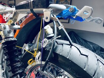
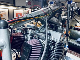
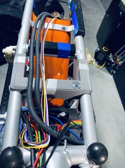
Some wires you can see in photos I have run long , in particular the red wire in photo 4, that is for the horn, I’m not sure if where I have it, will be it’s final resting place, so I gave my self a little wiggle room on that finished circuit. Photo 5 shows the final prototype seat support , where the front of the seat will fasten too, it also routes the cables to the battery, the rear indicators, and tail/ brake light . I’m pretty stoked with this clamp design , I will show that as a seperate post when I have printed the final units. Anyone brave enough to have printed parts on their bikes and think these parts can work for their bikes , I am happy to share the 3D files of them, on the condition no one makes any money off them.
I still can’t start the bike until my exhaust arrives , which grates that it is so late, but these are extraordinary times and people need to some slack cut for them, especially small companies and self employed blokes
 

Attachments

  • E253568F-9383-4E37-84CB-E23ED13A6345.jpeg
    E253568F-9383-4E37-84CB-E23ED13A6345.jpeg
    210.6 KB · Views: 103
  • 99E640D1-B78E-4336-8C93-FD6A3F18B8CE.jpeg
    99E640D1-B78E-4336-8C93-FD6A3F18B8CE.jpeg
    191.3 KB · Views: 102
  • D7B2687F-E58D-4C03-A85A-4AB49AF1D7C4.jpeg
    D7B2687F-E58D-4C03-A85A-4AB49AF1D7C4.jpeg
    189.5 KB · Views: 92
  • 59AAAB96-2EFC-457B-A52B-D97A43ED5842.jpeg
    59AAAB96-2EFC-457B-A52B-D97A43ED5842.jpeg
    153.2 KB · Views: 88
  • 9D83DF6E-71F2-4332-A63F-3CB31E438C08.jpeg
    9D83DF6E-71F2-4332-A63F-3CB31E438C08.jpeg
    207.3 KB · Views: 89
  • 31A672C3-FD45-411B-8B5F-4F67286149A7.jpeg
    31A672C3-FD45-411B-8B5F-4F67286149A7.jpeg
    156.2 KB · Views: 108
Back
Top