Building my Jota

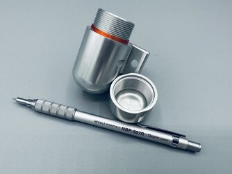
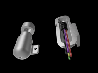
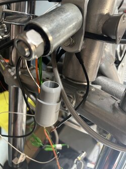
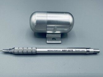
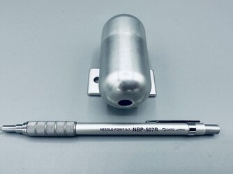
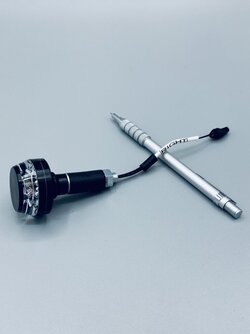
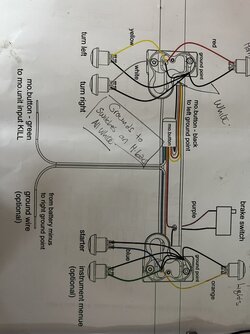
Some of the moto gadget work I have done with the electrics on the Jota. The wiring diagram is courtesy of revival cycles and their resources page, the difference is I use one button for both indicators, one tap is left indicator, two taps on the button is right indicator . I’m using aviation wiring for the earth wires on this, it has thin but high chafe resistance , and very good core wire, costs a ton, but for the few meters I need it’s not a deal breaker . The second photo is the canister I drew up for the m button, which converts signals into digital signals to the mo.unit blue . It needs to be shielded hence the thick aluminum walls, I was going to try and put it in one side of the clip ons , but I just wasn’t clever enough, all the wiring still runs through the clip ons,, but I then had to draw up canister to hold the m button , which mounts on the lower triple clamp, where the brake hose guide used to be. Last photo shows the proto type 3 d printed. The final one is being machined in Ali, I have a excess in the cap for a seal that I will print in tpu. The cap will have an M18 thread, with flats to nip it up . There will be cable protection in the form of black dyneema hollow braid ,where the wires exit the bottom of the canister .
 

Attachments

  • 9CB5AE3B-CB00-4D40-9E8C-479AA6EAE41B.jpeg
    9CB5AE3B-CB00-4D40-9E8C-479AA6EAE41B.jpeg
    109.4 KB · Views: 68
  • 949FD929-82AC-44C8-A260-47FF737B7FB8.png
    949FD929-82AC-44C8-A260-47FF737B7FB8.png
    227.6 KB · Views: 68
  • A6C4BBDF-63CE-4234-8982-5BFAED1C0E4F.jpeg
    A6C4BBDF-63CE-4234-8982-5BFAED1C0E4F.jpeg
    138.6 KB · Views: 68
Yes, of course. Those M-button thingys were designed for switch blocks that have their wiring inside the handlebar. They're supposed to pick up the wiring inside the handlebar and make installation simpler by running just one comms wire back to the M-unit. But if you have handlebar switches with external wiring (like the Suzuki-type switches on most Laverdas) then you have to find an alternative home for the M-button. Anyone without your fabrication resources (ie. most of us) would find that difficult.

Even if you'd converted your switches so the wiring would go inside the handlebars (not a difficult job), you'd still be up shit creek with Laverda handlebars because you can't simply pull the wires through the bars, as shown in the Motogadget diagram.

So, in my view, there's not much point in having the M-button with externally wired switches and Laverda bars (or clip-ons). It would be simpler to run the external switch cable bundles directly to the M-unit.

I reckon If I'd had to do a similar thing to what you've done, mine would have been a monkey wrench job using a bit of galvanised water pipe with threaded caps on the ends. Yours is a little more elegant than that.
 
One of the first modifications me and a mate did was to get rid of the horrible come-to-me Jesus handlebars on his GTE Bevel Ducati for some much more sensible Laverda Bars. We expected an easy 60-minute job till we noticed all the switch wires were run through those horrible handlebars from the Ducati Factory, one of the dumbest things ever. It was so tight we had to cut the wires out and splice them back together. A complete nightmare of a job that took many hours. It still scares me 40 years later.
 
Yes, of course. Those M-button thingys were designed for switch blocks that have their wiring inside the handlebar. They're supposed to pick up the wiring inside the handlebar and make installation simpler by running just one comms wire back to the M-unit. But if you have handlebar switches with external wiring (like the Suzuki-type switches on most Laverdas) then you have to find an alternative home for the M-button. Anyone without your fabrication resources (ie. most of us) would find that difficult.

Even if you'd converted your switches so the wiring would go inside the handlebars (not a difficult job), you'd still be up shit creek with Laverda handlebars because you can't simply pull the wires through the bars, as shown in the Motogadget diagram.

So, in my view, there's not much point in having the M-button with externally wired switches and Laverda bars (or clip-ons). It would be simpler to run the external switch cable bundles directly to the M-unit.

I reckon If I'd had to do a similar thing to what you've done, mine would have been a monkey wrench job using a bit of galvanised water pipe with threaded caps on the ends. Yours is a little more elegant than that.
I have the wiring inside the clip ons, but I think its too tight to have that as well as the m button in there. Im glad you think its an elegant solution, I figure I have spent so much time doing things, i may as well do it the best I can
 
The holder for my m.button that I designed , turned up today, originally I wasn’t going to anodize it, but I figured it was a good idea to, just to be sure and because I was anodizing some other bits and bobs. I had time enough to print the seal for cap today, that was a whole 88 seconds… but the printer is in use 24/7 these days with other projects, hopefully this weekend there will be a window to print the anti vibration sleeve that the m button will slide into when it’s home in its holder. in Any case it’s pretty cool seeing my little designs become reality.
 

Attachments

  • 1D1EEB96-DF14-446F-A09C-7F431E579AAD.jpeg
    1D1EEB96-DF14-446F-A09C-7F431E579AAD.jpeg
    90.7 KB · Views: 41
  • 75A667F2-B303-4501-B025-565502B9FFAA.jpeg
    75A667F2-B303-4501-B025-565502B9FFAA.jpeg
    87.6 KB · Views: 41
  • 88C67FDB-5F74-497F-89E0-9DF61696DDDC.jpeg
    88C67FDB-5F74-497F-89E0-9DF61696DDDC.jpeg
    94.8 KB · Views: 39
  • 7C95927B-EEFB-4668-AAEB-D1235F4C3F98.jpeg
    7C95927B-EEFB-4668-AAEB-D1235F4C3F98.jpeg
    89.6 KB · Views: 40
  • DC5E735F-2C7F-48B3-B6B8-15F2D77F15F2.png
    DC5E735F-2C7F-48B3-B6B8-15F2D77F15F2.png
    220.7 KB · Views: 40
The holder for my m.button that I designed , turned up today, originally I wasn’t going to anodize it, but I figured it was a good idea to, just to be sure and because I was anodizing some other bits and bobs. I had time enough to print the seal for cap today, that was a whole 88 seconds… but the printer is in use 24/7 these days with other projects, hopefully this weekend there will be a window to print the anti vibration sleeve that the m button will slide into when it’s home in its holder. in Any case it’s pretty cool seeing my little designs become reality.
Flash as all get out!
 
I’ve been head down and deep into wiring the Jota. For a while I wasn’t sure which connectors to use , I chose Deutsch connectors in the end , they seem the best thing out there to use, a learning curve when you aren’t familiar with them , is getting together all the parts and part numbers from seals , wedges and the like. I have chosen the swage crimp connections, that lead to having to buy an eye watering my expensive crimping tool, but the end result is worth it.
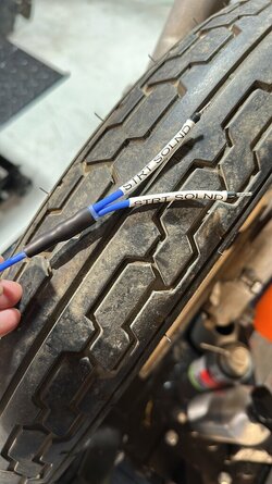
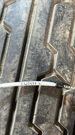
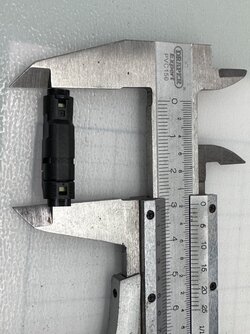
On the indicators, yes I am having them , as they are LED, I’m using the Molex mizu P25 connectors , they are tiny, but as the wires for the indicators are all .5mm square wire, you can get away with them , they slip nicely in the clip on. The last two photos are those connectors. The first photo shows the indicator with the male part of the connector on it. The indicators are “handed” as they project light front and rear. I splurged as well on a dymo printer that prints on heat shrink, it allows things to be well labelled, which will make future work on the bike much easier where the loom is concerned.

It’s really nice working with the right tools and making a nice ( to me) job of things. I may not be doing things the most logical way to others that are more experienced with bikes , but this all makes sense in my head !


1DF1B303-8C27-4229-AB55-BD3B9D0E1E1C.jpeg
 

Attachments

  • CE73B11A-7ED2-44B0-B949-363C18EE443D.jpeg
    CE73B11A-7ED2-44B0-B949-363C18EE443D.jpeg
    131 KB · Views: 35
  • 0C2672E5-BDB3-4DD2-80D3-86BB3D695F38.jpeg
    0C2672E5-BDB3-4DD2-80D3-86BB3D695F38.jpeg
    204.3 KB · Views: 36
  • 0B2B09AC-EB94-4F11-901F-0DCC69BB62B0.jpeg
    0B2B09AC-EB94-4F11-901F-0DCC69BB62B0.jpeg
    177.8 KB · Views: 33
  • E46C2D1E-43BC-40B6-9F95-ED19EFF97271.jpeg
    E46C2D1E-43BC-40B6-9F95-ED19EFF97271.jpeg
    198.8 KB · Views: 32
😎

You are using 0.5mm conductors yet the Black bootlace in photo #2 is for 1.5mm conductor


The wire in photo 2 is 2.5 mm square , 3 wires spliced into themselves then soldered and heat shrunk. These go from the starter solenoid to the m.unit. If that’s what you meant ?
 
That Dymo heat shrink labelling thing is a neat idea. Better than writing stuff on bits of masking tape and folding them into little flags on the cable, which is what I've been doing for donkey's years.
 
You should see behind my Tele sensurround sound system and Stereo, flags everywhere. Think 3c headlight internals x infinity. Plus power boards on power boards. No fires so far.
 
You should see behind my Tele sensurround sound system and Stereo, flags everywhere. Think 3c headlight internals x infinity. Plus power boards on power boards. No fires so far.
Sounds like mine, but I never labelled anything, it all just runs to the amps and one HDMI cable to the tv, which I kid myself makes it look tidy, but 9 speakers and their cables make it complicated
 
Blimey. My TV just has an internal speaker. Am I doing something wrong?
It's a smart TV that connects to the internet via Wi-Fi, but I still haven't figured out this streaming business. I guess I'm pretty much old school at home entertainment. I still use CDs for music. Never bothered upgrading to whatever is the latest thing. I could probably fit my entire CD and vinyl record collection on a memory stick.
 
Same here re TV, I only have 5 speakers but 2 are massive 1 mitre high multi-speaker cans. It's a bit of a home theatre setup. I have Foxtel Hi-Def, but it's getting to shit me. It used to be great with all the live bike racing and lots of first-run films but with all these streaming services Foxtel content is getting extremely thin and bloody expensive for what it is now. Very soon it's all going Satulight, the charmers have made that an offer you cannot refuse and I am really close to pissing it off.
 
Back
Top