Hi Chuck. That's a neat wheel conversion. Well done to get it all together.
Steve has given you a bit of sensible engineering input regarding the aspect ratio of a strut loaded in compression. He also said that "an engineer would analyse the loads and calculate the 'critical stress' and yada yada yada.... "
Naturally, as an engineer, I took that as a challenge.

I had to make a few assumptions: I allowed 150kg (half of the bike /rider combo) for the weight on the rear tyre.
Coefficient of friction between tyre and road of 1.0 max, so the breaking force at the tyre is also 150kg force (1500N).
I guestimated the lever arm radius from wheel axle to the torque arm mounting on the caliper to be 70mm, and the rear tyre radius to be 600mm.
A simple torque calculation reveals that the compressive load on the torque arm is around 12900N (roughly 1.3 tons force).
Now to the complicated bit. Using Steve's estimate of 200mm M8 rod for the torque arm, and applying Euler buckling formula for a pin-jointed bar, the buckling load for that rod comes out at around 5.8 tons, so you have a safety factor of more than 4. That would be considered ample for most engineering applications.
Of course all of the above is contingent on the assumptions being somewhere near reality. I think the torque arm looks longer than 200mm. I'd guess 400mm between the heim joints at each end. In that case the safety factor reduces to about 1, which means it's in imminent danger of buckling (a saferty factor of less than 1 means it'll fail). However, it has a threaded sleeve in the middle that would stiffen it up a bit so maybe you'll be OK.
BTW, the bolts through the ball joints are marginal. The shear load capacity of an M8 x grade 8.8 bolt is 14000N, so you only have a 1.1 safety factor there.
The torque arm attachment at the caliper end looks too close to the wheel axle. So an obvious improvement that you could make would be to attach the torque arm to the caliper mount at a greater radial distance from the axle. That would massively resuce the torque multiplication between tyre and torque arm, which would also reduce the load on the M8 bolts in shear. But that looks easier said than done because I can't see a handy attachment point in your photos.
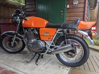
There is a nice attachment point further from the axle on the rear side of the caliper. I presume the wheel was the other way around in the Kawasaki (brake on right side) so maybe that's the bolt that Kawasaki used as the anchor point.
Is it possible to un-bolt the caliper from its mounting plate, flip the plate over and reassemble? That way, you'll have that bolt available in front of the caliper to fix your torque arm to.
If flipping the caliper plate isn't an option, then you could swing it around so the caliper is under-slung as someone else suggested. That'll allow you to use that attachment point further from the axle, with the rod in tension.
If neither of the above suggestions are acceptable, how about re-using the original Laverda/brembo mounting plate and caliper? You might have to modify it a bit to suit the new disk diameter and axial spacing, but that shouldn't be too difficult for a man of your ability.
Alternatively, you could take on Vince's timber engineering rule of thumb and use a lump of 4"x 2" hardwood.
Good luck with the project.



 I just wrote an mail to them, might hear back tomorrow. Let you know.
 . The rod is 210mm and 16mm dia.


