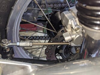
Rear wheel with rotor brake substitute

So
A 2 1/4"(?) rim is a bit narrow for a 130 tyre, 2.50 only marginal. 3.00 would be more suited, 3.50 even better. That would then allow the use of all the tread, ie, no 2" wide chicken strips! ;)

piet
Right, oops, that is the case, piet. Good spot.

Correction--I meant to write:
3CL rim width = 3 1/2 in
KLR rim width = 3 1/4 in
 
Great outcome, Chuck. I'm assuming you measured the rims with tyres off, inside edge-to-inside-edge? Considering a Borrani WM3 is std on 3Cs (can't recall the inch measurement), they must have been a lot narrower than the 3CLs at 3 1/2 (3 1/2 actually surprises me).

But that's a huge weight difference - glad i put you onto them!
 
Great outcome, Chuck. I'm assuming you measured the rims with tyres off, inside edge-to-inside-edge? Considering a Borrani WM3 is std on 3Cs (can't recall the inch measurement), they must have been a lot narrower than the 3CLs at 3 1/2 (3 1/2 actually surprises me).

But that's a huge weight difference - glad i put you onto them!
Ah, not quite, I measured outside rim edge.
So, whatever the Laverda is, the KLR is overall 1/4 in less.
However, both rims are rated for 130/80 tyres.
 
Kawaverdasaki brake system done. (I'll replace the threaded bracing rod later)
 

Attachments

  • PXL_20210930_060828341.jpg
    PXL_20210930_060828341.jpg
    142.1 KB · Views: 42
  • PXL_20210930_081543049.jpg
    PXL_20210930_081543049.jpg
    204.3 KB · Views: 42
Hi Chuck.

I'm sure you know this, but that stay-rod would be much better in tension - so when replacing the studding, use some tube - largish diameter. I am also a bit worried about where the studding enters the calaiper - no joint means the stay rod have torque applied. The section where it enters the caliper will be badly strained.
 
Hi Chuck.

I'm sure you know this, but that stay-rod would be much better in tension - so when replacing the studding, use some tube - largish diameter. I am also a bit worried about where the studding enters the calaiper - no joint means the stay rod have torque applied. The section where it enters the caliper will be badly strained.
I'll have to put up a better picture. I think you are not seeing the whole arrangement correctly. The rod is in compression which is what I wanted. The rod is attached at the caliper with M8 in shear, very strong. (The rose joints may not be apparent) The caliper is also mounted on an alloy piece connected to the axle. The whole arrangement is triangular, my favourite structure for strength! The 3 sides are: swing arm, compression rod, original caliper mount. Needs to also be adjustable for chain wear.

Better pic will help.
 
Last edited:
Yes, it looks like the rod goes straight into a thread in the caliper, but I can see that the caliper end is actually the same as the front section.Any way you can mount the caliper underneath? Would look a lot tidier (IMHO). M10 rose joints in tension and M8 in shear.
 
Yes, it looks like the rod goes straight into a thread in the caliper, but I can see that the caliper end is actually the same as the front section.Any way you can mount the caliper underneath? Would look a lot tidier (IMHO). M10 rose joints in tension and M8 in shear.
Appreciate your suggestions, but I much prefer the caliper above the axle for a number of advantages.
It is protected, up an out of harm's way, and in keeping with the original Lav configuration (and similar to most other bike configurations).
The likelihood of road dirt accumulation in the caliper is reduced, and it's not upside-down catching stones. This also minimizes the length of brake line so I can use what is currently there.
The M8 rose joints both have equal shear force with the rod in compression when braking forward. (Minor tension if braking rearward). I also want to use the existing welded Lav M8 thread attachment bracket on the swingarm.
FInally, I do much of my riding off-road ( on the Tiger 800XCX that is, not the Lav!) and I'm wary the damage that can be done on parts lower down on the bike. E.g. mud, water/dirt spray, small stones, wet tar, roadkill😉)
 
After many 1000's of km with low-hanging rear calipers, the only disadvantage I've experienced is slightly exagerated pad wear, possibly through a bit more rain water passing through the brake. But, not enough to worry about, even the discs seem to hold up normally.

As Haggis suggested, that rod should be replaced with a substantial tube, especially if the point at which it is attached at the caliper end is final. Those leverage ratios are quite unfavourable.

piet
 
I also like the ease of wheel fitment as a reason, I hate juggling 2 or 3 things at the same time to line up when fitting wheels. Where in Oz are you, Chuck.
 
I do not like push rod, prefer pull.
M8 fixing at the original bracket of the swinging arm is critical, bending, shear forces. Fixing of the rod to the caliper os not clear visual, I don‘t see wheather it is spherical.
 
I've listed above what I think are a number of advantages to mounting the brake above the axle, and I also believe the configuration is more than sufficient to ensure safe use.
I am open to other ideas, but personal aesthetics choice aside, I can't see any compelling reasons or advantages to mounting the brake below the axle. I only posted this thread to share info. 😉

Or another way to say it: Voltaire, the French writer, said, “The best is the enemy of the good.”

Accordingly, I'm done, now I'm going to ride it like I stole it!
 
Last edited:
Please take the comments as constructive and kindly Chuck. There is nothing more important than brakes on a motorcycle.

It's your call, but in my opinion there are aspects of your design that are dangerous. One example - you appear to be relying on the welding between the nut and bracket to hold the front spherical. If so, that is unwise. I'm not just criticising like a moronic forum troll - I am concerned.
 
Please take the comments as constructive and kindly Chuck. There is nothing more important than brakes on a motorcycle.

It's your call, but in my opinion there are aspects of your design that are dangerous. One example - you appear to be relying on the welding between the nut and bracket to hold the front spherical. If so, that is unwise. I'm not just criticising like a moronic forum troll - I am concerned.
I understand Haggis, and I appreciate yours and all of the comments on this forum and that's why I posted so I can get good feedback, and also share anything someone might want.
I did explain that the current design is a prototype. I will take your comments into consideration on the final design. It's just hard to get materials right now with lockdown so i've had to make do with the hardware store. Thanks for your concern
 
Hi Chuck,
just my remarks and input, you may decide as you like. Forces at the brake caliper are not so high if you calculate but some engineering rules should be respected.
Push rods should be stiff and free of bending forces an they tend to knick..
Pull rods don‘t. 😄
 
Chuck, thanks for this thread, that rear wheel looks like a really nice option. I have a basketcase 3CL project bike for which I only have a frame and engine, and would like that to have spoke wheels, so I might take a look at that when I ever get around to it.

Regarding the rear brake stay, I'll also chip in, also not trying to be a troll, just concerned.

The issue with it being in compression is buckling (or column) failure. A long slender rod can fail under considerably lower stress than the same thing in tension. Rule of thumb is that column failure should be considered when length (L) / radius of gyration (k) > 30. If your compression stay is M8 and guessing 200mm long, then L/k= ~117.

At this number an engineer would then analyse the loads and calculate the 'critical stress' and yada yada yada.... and most likely come back with the same result as some experienced 'eyedrometers' here, which is that it's too long and thin. A larger diameter solid ally rod tapped each end would be a pretty simple solution. I can assist if you don't have the capacity to do it or a local engineering shop handy.

As Hag pointed out, the connection to the swingarm is also worth a closer look, as the bracket and particularly the welded nut were not originally intended for loading in that direction. The nut was originally only a clamp screw, the load from the caliper stay being directed downwards by the caliper carrier on the bracket. However my eyedrommeter is more concerned about the stay for starters.
 
Hi Chuck,
just my remarks and input, you may decide as you like. Forces at the brake caliper are not so high if you calculate but some engineering rules should be respected.
Push rods should be stiff and free of bending forces an they tend to knick..
Pull rods don‘t. 😄
Understand, this is my prototype only. My longer term intention is to use a solid bracket bolted on at both caliper bolts and running through the swingarm mount like the Laverda was. Gives the stiffness, no rotation, bracing, and allows simple wheel position adjustment.
I need to source materials.
Chuck, thanks for this thread, that rear wheel looks like a really nice option. I have a basketcase 3CL project bike for which I only have a frame and engine, and would like that to have spoke wheels, so I might take a look at that when I ever get around to it.

Regarding the rear brake stay, I'll also chip in, also not trying to be a troll, just concerned.

The issue with it being in compression is buckling (or column) failure. A long slender rod can fail under considerably lower stress than the same thing in tension. Rule of thumb is that column failure should be considered when length (L) / radius of gyration (k) > 30. If your compression stay is M8 and guessing 200mm long, then L/k= ~117.

At this number an engineer would then analyse the loads and calculate the 'critical stress' and yada yada yada.... and most likely come back with the same result as some experienced 'eyedrometers' here, which is that it's too long and thin. A larger diameter solid ally rod tapped each end would be a pretty simple solution. I can assist if you don't have the capacity to do it or a local engineering shop handy.

As Hag pointed out, the connection to the swingarm is also worth a closer look, as the bracket and particularly the welded nut were not originally intended for loading in that direction. The nut was originally only a clamp screw, the load from the caliper stay being directed downwards by the caliper carrier on the bracket. However my eyedrommeter is more concerned about the stay for starters.
Thanks for the analysis, I always say you can't manage what you can't measure!
I do have a solid rod as an option, and I would use the Laverda swingarm clamp as intended. But, ( see my last design intention above) another design is to use both caliper bolts to also prevent rotation.
If you do use the KLR caliper above the axle--Notice I cut off the excess 'slide' arm because it is on the opposite side.
BTW, I used all the OEM Lav axle arrangement except I replaced the l.h. spacer with a smaller 8mm width spacer.
 
Last edited:
Just for a giggle, the general rule for the slenderness ratio in Timber for a column is 40 as to 1. Haven't remembered that for a long time, thanks Steve B. That's if you make it out of Black Butt. You did incredibly well getting this done so bloody fast. Getting stuff done fast here isn't common.If your around Sydney we have a club ride coming up as soon as we leave lockdown, its a day run-up The Putty. Come along if you like. Plenty of brake testing there.
 
Hi Chuck. That's a neat wheel conversion. Well done to get it all together.

Steve has given you a bit of sensible engineering input regarding the aspect ratio of a strut loaded in compression. He also said that "an engineer would analyse the loads and calculate the 'critical stress' and yada yada yada.... "
Naturally, as an engineer, I took that as a challenge. :)

I had to make a few assumptions: I allowed 150kg (half of the bike /rider combo) for the weight on the rear tyre.
Coefficient of friction between tyre and road of 1.0 max, so the breaking force at the tyre is also 150kg force (1500N).
I guestimated the lever arm radius from wheel axle to the torque arm mounting on the caliper to be 70mm, and the rear tyre radius to be 600mm.
A simple torque calculation reveals that the compressive load on the torque arm is around 12900N (roughly 1.3 tons force).

Now to the complicated bit. Using Steve's estimate of 200mm M8 rod for the torque arm, and applying Euler buckling formula for a pin-jointed bar, the buckling load for that rod comes out at around 5.8 tons, so you have a safety factor of more than 4. That would be considered ample for most engineering applications.

Of course all of the above is contingent on the assumptions being somewhere near reality. I think the torque arm looks longer than 200mm. I'd guess 400mm between the heim joints at each end. In that case the safety factor reduces to about 1, which means it's in imminent danger of buckling (a saferty factor of less than 1 means it'll fail). However, it has a threaded sleeve in the middle that would stiffen it up a bit so maybe you'll be OK.

BTW, the bolts through the ball joints are marginal. The shear load capacity of an M8 x grade 8.8 bolt is 14000N, so you only have a 1.1 safety factor there.

The torque arm attachment at the caliper end looks too close to the wheel axle. So an obvious improvement that you could make would be to attach the torque arm to the caliper mount at a greater radial distance from the axle. That would massively resuce the torque multiplication between tyre and torque arm, which would also reduce the load on the M8 bolts in shear. But that looks easier said than done because I can't see a handy attachment point in your photos.

There is a nice attachment point further from the axle on the rear side of the caliper. I presume the wheel was the other way around in the Kawasaki (brake on right side) so maybe that's the bolt that Kawasaki used as the anchor point.
Is it possible to un-bolt the caliper from its mounting plate, flip the plate over and reassemble? That way, you'll have that bolt available in front of the caliper to fix your torque arm to.
If flipping the caliper plate isn't an option, then you could swing it around so the caliper is under-slung as someone else suggested. That'll allow you to use that attachment point further from the axle, with the rod in tension.

If neither of the above suggestions are acceptable, how about re-using the original Laverda/brembo mounting plate and caliper? You might have to modify it a bit to suit the new disk diameter and axial spacing, but that shouldn't be too difficult for a man of your ability.

Alternatively, you could take on Vince's timber engineering rule of thumb and use a lump of 4"x 2" hardwood. :)

Good luck with the project.
 
Last edited:
Back
Top