Reviving a battered 1200

Jon is right. Many might run the comp tester on a cold motor with the throttle closed, open throttle, hot motor, oil in cylinders, no oil in cylinders ... and base all their info on one result. Several different ways to get a reading, so numerous ways to interpret a result incorrectly.
 
So why no love for a leak down compression test? It is much more informative as to points of failure than the cranking type. Even just putting pressure to each cylinder through an air fitting welded to a spark plug shell will be enough to diagnose. And an actual leak down gauge will allow comparing cylinder to cylinder.
 
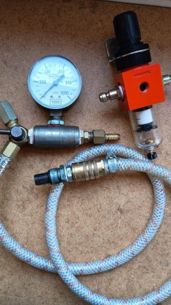
As you say Cam, speak for myself, made up an elaborate leakdown test jig, basically a compressed air feed with two gauges on either side of a 0,7mm hole union, with a hp side feed shutoff to watch the actual leak down on the cylinder head side, the premise as i could best glean from engineering information, the leak will be seen on the cylinder side gauge. Kind of dangerous depending on where the piston is and how you lock the crank in increments as the piston is drawn down the bore. Inlet and exhaust poppet valve seat leaks are readily heard in the carby or exhaust.

Even put a regulator on the HP feed side, for a stable high side gauge reading. May well be i have it wrong though what i was hunting for was scored bores, and leak from a damaged bore. Now you just use a fancy smart phone with bore scope camera.... i gave up the leak down test as a reliable test jig here...j piccy of what remains of my diy leakdown test jig, found other uses for some of the bits
 

Attachments

  • Leakdown.jpeg
    Leakdown.jpeg
    154.7 KB · Views: 9
Last edited:
I've never seen an adequate explanation of what a set of leak down gauges actually does.
You apply a known air pressure to the cylinder, usually 100 psi for ease of calculation and measure the pressure in the cylinder with a second gage. That is then compared to the inlet pressure in terms of a % of leak down. If the incoming pressure is 100psi and the cylinder holds 97 psi then the sealing is 97%. A good engine should be from 90% to 99% with race engines expected to be over 95%. The engine must be at TDC with both valves closed which is not always easy to ensure.

The true benefit is in the diagnostic useage of the leaking air. If you hear air hissing out the exhaust pipe, it’s the exhaust valve, the inlet: it’s the intake valve, the crankcase breather: the rings and the valve cover: the valve guides.

A simple diagnostic tester can be cobbled up from a spark plug shell with an air nipple welded to it if you aren’t concerned with the % of leak down and just want to introduce air pressure into the cylinder. In this case you can use a lot lower air pressure also.

In the US, Harbor Freight sells a perfectly decent tester for $99, and I’m sure other countries have similar outlets selling cheap Chinese tools as well.

The two gages are screwed into an alloy block with a small orifice between them to allow air to be restricted. You set it up to test by adjusting the inlet pressure to give 100psi on the gage upstream of the orifice before connecting to the cylinder. This is with the spark p,uh fitting uninstalled, then when screwed into the spark plug hole it will read the pressure of that cylinder. If you use 100psi on the inlet then 97 psi in the cylinder is 97% sealing, no calculation needed.

Corrected: to clarify how it works!
 
Last edited:
Yes understand the basics outlined by you Alzero, differential pressure jig as such, the percentage calc has me not so sure, how do you hold 100 in the example and then measure a "leak ratio" ie there will be a constant leak ( now LP side ) as likely as not and the gauge cylinder side will drop in a decreasing mode. If you start with 100 on both sides then both gauges will drop hence why i used as small an orifice i had here, to mitigate the possible decrease on the HP "charge side", as the now LP side starts to leak after precharging and source pressure removed ( via a shut off valve ).

Some challenge describing this in simple form, the small orifice is hoped to be small enough to allow the LP side to indicate a "percentage" reading, ie not be resupplied by the HP side as the LP side leaks away. The 0,7mm will be ( hopefully significantly ) less than the sum of the leakages gaps or paths in the tested cylinder, in order to render a somewhat quantifiable measurable calibrated leak amount or degree.

May well be me not comprehending how the commercial leakdown test jigs are constructed, it is the verifiable methodology that appears unclear, hence my alignment with Cam. j

BTW while the piston is at TDC ( plus or minus valve overlap ) then the leak test can be used all the way down of the cylinder fuel burning gas expansion ( power stroke ) hence check for bore damage or triangulation of the bore top to bottom, even the oft read "barrel" shaped worn bore(s)
 
Last edited:
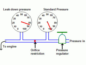
You keep the supply air pressure on at all times after setting it on the first gage. The restrictor is to allow the pressure build up on the supply side. On an engine with zero leakage both gages would read the same with no air passing through the orifice.

Wikipedia has an excellent explanation of how this works which is where I found this diagram. The article also gives the suggested orifice size for various displacement engines should you wish to make one again.

I corrected my original post above: it has been a long time since I used one of these and my memory failed me for a moment.
IMG_0170.gif
 
Last edited:
The leak down test is a relative test meaning not absolute and an indication of the leakage of the piston/cylinder head combo. It helps to indicate the culprit, but in my case, I also used a leakdown test, it just indicated some blowby, < 10%. the signal is hen traced through listening the exhaust, crankcase ventilation and inlet. Luck for the previous owner, as it was ok. The cylinder liners found to be however tapered > 0.10 mm and unround by 0.1 mm. I also found the piston gaps HUGE, . 1.4 mm for all of them. A sick engine which can be indicated slightly worn but serviceable. My luck 😔 , but we move on. New liners and piston rings will fix that, pistons are all checked and are in almost new condition. I think the previous owner just dropped in new pistons and some rings (I have never seen gaps likes this before, and still a reasonable compression an leakdown test).The story goes on...
 
In this case, when the compression is reasonable and the leak down is showing good test results, it shows that these test do not assess the condition of the cylinder/piston/liner 100%, but nearer to 85%. Compression should be 10 Bars, but 8 will run the engine. The taper in the cylinder and the piston rings gaps made sure all working gasses could escape with the cylinder 20% over TDC.
When I pointed out the overpressure from the case to the previous owner he said: "they all do that". This is correct to some height, the irregular pulses from the undulating pistons, create one small volume pulse ( middel cylinder going down) and one big one ( both outer cylinders going down). The ball in the crankcase breather helps by closing when there is under pressure in the cases. Im my bike the ball was split in half, not helping.
More to come
 
You apply a known air pressure to the cylinder, usually 100 psi for ease of calculation and measure the pressure in the cylinder with a second gage. That is then compared to the inlet pressure in terms of a % of leak down. If the incoming pressure is 100psi and the cylinder holds 97 psi then the sealing is 97%. A good engine should be from 90% to 99% with race engines expected to be over 95%. The engine must be at TDC with both valves closed which is not always easy to ensure.

The true benefit is in the diagnostic useage of the leaking air. If you hear air hissing out the exhaust pipe, it’s the exhaust valve, the inlet: it’s the intake valve, the crankcase breather: the rings and the valve cover: the valve guides.

A simple diagnostic tester can be cobbled up from a spark plug shell with an air nipple welded to it if you aren’t concerned with the % of leak down and just want to introduce air pressure into the cylinder. In this case you can use a lot lower air pressure also.

In the US, Harbor Freight sells a perfectly decent tester for $99, and I’m sure other countries have similar outlets selling cheap Chinese tools as well.

The two gages are screwed into an alloy block with a small orifice between them to allow air to be restricted. You set it up to test by adjusting the inlet pressure to give 100psi on the gage upstream of the orifice before connecting to the cylinder. This is with the spark p,uh fitting uninstalled, then when screwed into the spark plug hole it will read the pressure of that cylinder. If you use 100psi on the inlet then 97 psi in the cylinder is 97% sealing, no calculation needed.

Corrected: to clarify how it works!
Yes that is what i built, my picture demonstrates. Described in your posting and mine, saying the same thing. Used some 20+ years ago, it was a less than convincing test device as to calibrated leakage, as a basic tool to pump air into a cylinder it will work, as to deriving a calibrated ratio of stored pressure and measured low pressure ( leaking ) escapes me. May well work as a derived cylinder to cylinder appraisal same engine, as to being a universal measuring device, better men than me can demonstrate the real world application. Maybe i am strange.... known to happen, j.


** Just seen the other postings and diagrams, appreciate the efforts expended, remain my position that the ratio of orifice to measured cylinder is a crucial factor, too large the smaller leaks will be swamped, too small and the measured cylinder reading will collapse. The is the analogy of pressure and EMF, for a fixed resistance, the actual current flow is not linear, it is a square law function, E squared on R R being the orifice, then i would expect the decreasing pressure against the cylinder leaks will also be a non liner transfer function. Pneumatic engineering folk out there correct me, seem to recall it is the same, electricity and Pneumatics. Used to work on electro pneumatic machinery in the early 1970's. Been a while for myself also.
 
Last edited:
For what it is worth this is the standard method of assessing the health of an ICE aircraft engine. The size of the orifice is calculated based upon the bore of the engine, as is the pressure of the air supply. A lot of thought has gone into this and its effectiveness has been accepted in the industry for nearly 100 years or even more. For all I know, Glenn Curtis’s and the Wright Brothers were using it!
 
Pertinent aspect, orifice matched to known cylinder specification, something i anticipated yet not covered or stated in the sources available at the time. Not that important here leak down, defer to others whom find it of reliable value if not virtue, a grin.

Light aircraft engine design and testing is pivotal in the early design work of the IIS ignition and lesser so, the replacement polyphase alternator upgrade i designed in the late 90's for the 180 series 1 motors. Enormous respect for the research and data available at the time, all from the USA j
 
As you point out, compression tests will only give an indication. Leak-down has the possibility to localise, at tdc. If either starter motor or leak-down give unacceptable figures you can plan the engine stripdown. The only way to really know is dismantle and measure.
I have seen engines with good spin-over figure but badly sealing valves a leak-down would have shown up.
 
Yes, I understand all that. Two pressure gauges and all. But on all the units I've seen, the downstream gauge is calibrated in % which makes no sense to me. Percentage of what? And don't tell me that the percentage of the air that leaks out. If that was the case it would be accumulating the non-leaked air somewhere. It's a steady state flow scenario, so 100% of the supplied air leaks out somewhere. Maybe it's the % pressure drop from the supply gauge. But no write-up on the leak down tester that I've read has ever stated that. I dunno who writes the operating instructions for these things, but nobody ever says what the % gauge is actually measuring. We're supposed to just not be bothered by that and assume the manufacturers of these things know what they're on about. Sorry, that's not good enough.

The use of two pressure tapping points is a pretty normal way to measure flow rates in many applications. The leak down apparatus is clearly a flow measuring device. In this case it measures the flow through the internal orifice in the unit itself. But no flow rate is ever expressed in %. Why isn't it calibrated in litres/second or CFM? It would make more sense to me to simply have two identical gauges as in Alzero's diagram. At least I could draw some conclusion from those readings.

It's perfectly sensible to apply a steady, known pressure to an engine cylinder and see how fast it leaks out. But I'd want to see a reading in CFM or some other flow unit that can be compared to a chart of what to expect, and can be related to other engines. I don't want a fucking meaningless % reading.

I actually own a leak down tester but I never use it. I tried to use it once but the stupid apparatus did nothing that I could make any sense of. The gauges are not the same. The second (%) gauge is more sensitive than the supply pressure gauge so I have no idea what pressure or flow rate it's reading.
 
This pre-charging of a sealed cylinder is a leak away tester in its crudest form, pressurise the cylinder and audible/listen for leaks or watch the ONE incoming pressure gauge indicate a discharge of air, when the source supply of compressed air is shut off ( means no air leaks in any of the test apparatus as connected ) that i can live with, as a basic diagnostic unreferenced tool.

Ascribing an actual percentage value of a cylinder air loss against a feed supply will need way more than one tool fits all, that about it for me. May your workshop be blessed with all manner of success, i mean that 100% minus 10%.... its the leaking sceptic in the room...j.

*** Just read the Wiki page on leakdown testers et al. after my replies above. Vindicates Cam and my perspectives, as to what is being measured and how, not a perfect discourse on "leak down" test theory, rather, a broad view from one or some authors and a few references as quoted. HTH
 
Last edited:
Hi Cam,

Most of us buy unbranded leakdown testers from "that country", in my case it was also total junk and I had to replace a lot of it. When in good order and operated correctly it is a useful comparative tool. If they were useless, they would not be the standard procedure adopted by the FAA.

The flow across the (correctly dimensioned) orifice will indeed work out to a real flow rate but for the purposes of the test it is not critical, as it's a comparative test. I presume keeping it simple removes a bunch of 'human factors' from the process (and keeps the tools affordable).
The orifice as specified by the FAA for 'small' engines is 0.040 x 0.25in with 60degree approach angles. For our smaller cylinders there's an argument for a smaller and/or longer orifice to more greatly influence the downstream reading, but it works fine.

Percentage of what? And don't tell me that the percentage of the air that leaks out. If that was the case it would be accumulating the non-leaked air somewhere.
As already stated, it's just % difference between upstream and downstream pressures. The gauges are only calibrated in the way they are to make it easy for dummies to read. Your pedantry is admirable and it's not "lost", it's just a convenient indication of how much is leaking out of the test cylinder to atmosphere.

It would make more sense to me to simply have two identical gauges as in Alzero's diagram. At least I could draw some conclusion from those readings.
To make my chinese tester useful I replaced both gauges with identical SMC guages and replaced the non functioning reg with an SMC reg. I also remade the orifice part to FAA specs. Basically I bought a red blow-moulded case for $100. :D
It now works well, gives an output that can be interpreted, and allows you to identify where any leakage is occurring. You could quantify that to a degree with baloons taped over inlet & exhaust ports and crankcase breather. FAA specifies up to "25%" past rings and zero elsewhere.

If you're bored... :D
 
I'll bite, how do you know that your actually losing a verified 10% or any thing like that, you would need a calibration jig that would have a known 10% ratio of leak to pressurised void, nee cylinder in this case. Then check your "leak down tester" against a calibration jig. No different to electronics. For known traceable measurements you will need to trace back to a known reference device or jig.

Would a void of 1 litre then leak 100ml of fluid over what time for a 10% leak or loss? Not from where i come from, like water clocks of the Roman era, the pressure lessened as the vessel drew down the water, yielding a non linear flow. You can add a constant pressure device ( as the second stage of a water clock does ) a given, you then would require the measuring device under test that is known to indicate that leak by 10% by calculation and verified on the in use "leak down tester", measured

By implication the orifice has to match exactly the void or cylinder under test, parameters. In order to state with a degree of certainty exactly how much air in this case is lost to imperfect void or cylinder under test. Ascribing a general orifice may get you in the ball park, perhaps, though is a long way from an uncalibrated measuring device abilities.

Furthermore, if your looking for a few percent of full scale deflection ( valid in this application as it is in electronics ), then your accuracy required can be calculated. Moving coil meter has an accuracy stated as say 2.5% at full scale deflection, as the needle moves towards the starting end of the scale this accuracy is not maintained at 2.5%, it degrades dependent on quality of the movement.

Extrapolating to pressurised device, and actual flow of air HP side to LP side of the orifice at what pressure do you measure this “accurate” percentage leak? The nett losses are changing with applied pressure. Amount of pressure applied to rings and poppet vales will vary the actual sealing, does a poppet valve seat seal the same from 0psi to peak cylinder pressure at combustion, maybe, it is not as such a certainty to seal across a broad rang of test and working pressure to my knowledge.

Leak down tester with “calibrated” percentage reading can be achieved under strict known conditions, that is not what is being discussed here. j
 
Last edited:
Yes, I understand all that. Two pressure gauges and all. But on all the units I've seen, the downstream gauge is calibrated in % which makes no sense to me. Percentage of what? And don't tell me that the percentage of the air that leaks out. If that was the case it would be accumulating the non-leaked air somewhere. It's a steady state flow scenario, so 100% of the supplied air leaks out somewhere. Maybe it's the % pressure drop from the supply gauge. But no write-up on the leak down tester that I've read has ever stated that. I dunno who writes the operating instructions for these things, but nobody ever says what the % gauge is actually measuring. We're supposed to just not be bothered by that and assume the manufacturers of these things know what they're on about. Sorry, that's not good enough.

The use of two pressure tapping points is a pretty normal way to measure flow rates in many applications. The leak down apparatus is clearly a flow measuring device. In this case it measures the flow through the internal orifice in the unit itself. But no flow rate is ever expressed in %. Why isn't it calibrated in litres/second or CFM? It would make more sense to me to simply have two identical gauges as in Alzero's diagram. At least I could draw some conclusion from those readings.

It's perfectly sensible to apply a steady, known pressure to an engine cylinder and see how fast it leaks out. But I'd want to see a reading in CFM or some other flow unit that can be compared to a chart of what to expect, and can be related to other engines. I don't want a fucking meaningless % reading.

I actually own a leak down tester but I never use it. I tried to use it once but the stupid apparatus did nothing that I could make any sense of. The gauges are not the same. The second (%) gauge is more sensitive than the supply pressure gauge so I have no idea what pressure or flow rate it's reading.
Your over thinking it- pump your tyre up and spit on the valve, it bubbles- you’ve got yourself a leak down tester!
 
'spose a calibration device could be made, taking the imperial path, source impedance ( that is what the orifice is ostensibly in the leak tester itself ), as indicated above say 40mils then a ratio of 10 to 1 could be applied yielding a void ( say cylinder ) of 400mils in internal diameter. Could make the leak orifice on the calibrator screw thread and use a range of known accurate carby jets, to assess actual leakage indicated. Nominal orifice in mm converted to mils in respect of the calibrator cylinder, depth of the cylinder would have to be compensated for, a calculation beyond my skills, perhaps it may not be a factor as at the opposite end of the incoming test hose connection, my thought is that as long as the ratio of internal bore to orifice bore was known the actual leak could be verified. Shout me down on this latter assumption, not all that comfortable on this aspect of the design.

Have not covered resolution of the indicating moving needle devices, or the matter of matched pair of gauges ( as is done in electronics ), your ostensibly looking to resolve small increments of meter movement at varying positions of the calibrated scale behind the needles, 1 or 2% would be beyond the nominal 2.5% FSD ( near 100% resolution error possible ) let alone mid scale and positions in between. At times less than FSD can be up to and more than 10-20% error, resolving small percentages with an inbuilt scaling error of 10 or 20% yields the device more or less just a comparative device and not an absolute device. Enestee0 made this point also as i read his reply.... time to cook din din... 10% decline in cooking quality would be a win, more in the 90% loss....a wry smile here. j
 
Back
Top