
Shorted drive transistor Cam, 3 pin device, think i used a PNP due to the quirk in the quad comparitor, see if i can scare up the hand drawn schematic, LM339 comparator, LM431 programmable Voltage reference some resistors as divider chain, and a drive transistor. The later has to carry the incandescent lamp surge current, between 6 and 10 times normal lit current, hence the driver transistor get a flogging, BD139 or BD140 is the cure.... then you will mis it not glowing...it would drive me to distraction as it is on your ride.... 3 solder joints Cam...you can do it... post you a couple of transistors, maybe a surge limit resistor in series with the output wire to the lamp.... remain at your disposal.... jIt's still on the bike John, but no longer works. Red light stays on all the time. It only worked for a few months, so I installed a voltmeter. I submit the photo below as exhibit 1. Note that at 2000rpm the system voltage is 14.3V, but the "GEN" light remains on.
One of these days I'll remove the charge light gizmo. Do you want it back to diagnose its failure mode?
View attachment 82299

You are using an out of date browser. It may not display this or other websites correctly.
You should upgrade or use an alternative browser.
You should upgrade or use an alternative browser.
when you are your own dreaded previous owner
- Thread starter Paul LeClair
- Start date

motoddrob
Hero member
- Location
- S/W Australia
That connector was suss right from the start!
Mentioned to you in the dark days of chronic low volts, Rob, the reason may well be simple and very obvious with that inscrutable hindsight... a wry smile here. BTW i covered in that diatribe post, a possible circuit to allow proper charge current measurement for an AC shunt RR, would work on a series reg FET RR also. Hall Effect current shunt, here you go, simple application note....That connector was suss right from the start!
Using Allegro Current Sensor ICs in Current Divider Configurations for Extended Measurement Range
Appliction Note on Using Allegro Current Sensor ICs in Current Divider Configurations for Extended Measurement Range ( current transformer, current transducer, dc current sensor, low current sensor, hall effect transducer)
 www.allegromicro.com

78jotadave
Hero member
No Rob my Ignitech is the ignition system supplied by the company in the Czech Republic, it retains the original two pickups and the standard charging system. Red utilizes the Ignitech module but uses a completely new (different) pickup system and a Kawasaki charging system.My 1200 TS had a charging light till I upgraded to a ZZR250 3 phase alt which then requires a 3 phase RR so no charge light.
What is the charge system fitted to your 1200 Dave?? I'd have thought the Red supplied ign upgrade would come with the 3 phase alt as mine did.

- Location
- Calgary, Alberta, Canada
Really? Does your 1200 have a working "GEN" light in the dash?
I'd have expected the 6th (brown) wire to be a voltage sense wire as John suggested. I'm not aware of any 3-phase RR with a generator light output.
Hi Cam
I am pretty sure the r/r on the 79 1200 came from John at IIS back in the day. Since the beginning i have had that brown wire hooked up to the generator warning light wire, but it has never come on……
The r/r I took from teh RGS and temporarily hooked up on the 79 1200 works fine, a steady 14.2 volts.
The Shindegen MOSFET I ordered will be weeks getting here, yesterday I ordered from Amazon on one day free Prime delivery a cheap $16 r/r listed for an old Suzuki 1000, going to stick it on and see how it works as a temporary space filler……
Glad the gen light did not come on Paul, you actually had a win for the wrong reason, have to check though i believe the supply side to the gen lamp is Battery 12V switched. By happenstance you had via a low impedance lamp, "sense 12V" correct! Had the lamp failed you would have lost charging or worse gross overcharging.... Mazing.... jHi Cam
I am pretty sure the r/r on the 79 1200 came from John at IIS back in the day. Since the beginning i have had that brown wire hooked up to the generator warning light wire, but it has never come on……

Andy
Hero member
- Location
- Auckland, roughly
So Paul’s RR may still be ok? If the sensing input is connected?
motoddrob
Hero member
- Location
- S/W Australia
Hi Dave, for some reason I thought Red had supplied the ignition. Using the original p/u and alt explains why you have a gen light.
Seems the original RR is actually faulty Andy, Paul is methodical, and diagnosed it correctly, if there was a wire for wire swap between old RR and replacement from other working bike, as can be best attested. jSo Paul’s RR may still be ok? If the sensing input is connected?

Dellortoman
Hero member
- Location
- Tasmania, Australia
For some reason I find that amusing. Completely wrong assumption and connection by Paul, but it worked by dumb luck. He's on a steady learning curve with electrics and will know better next time.Glad the gen light did not come on Paul, you actually had a win for the wrong reason, have to check though i believe the supply side to the gen lamp is Battery 12V switched. By happenstance you had via a low impedance lamp, "sense 12V" correct! Had the lamp failed you would have lost charging or worse gross overcharging.... Mazing.... j

- Location
- Calgary, Alberta, Canada
my $16 regulator rectifier has arrived from Amazon with free one day delivery. Does not have any brand identifier on it. Looks pretty much identical to the one I recently swapped on to the 79 1200 from my 84 RGS.
going to temporarily install my $16 cheapo r/r while I wait for the expensive Shindegen Mosfet r/r to clear customs. Will then test voltage regulation with the cheapo r/r. This one purchased from an Amazon vendor is listed as suitable for 80's Suzuki 1000.
going to temporarily install my $16 cheapo r/r while I wait for the expensive Shindegen Mosfet r/r to clear customs. Will then test voltage regulation with the cheapo r/r. This one purchased from an Amazon vendor is listed as suitable for 80's Suzuki 1000.
Attachments
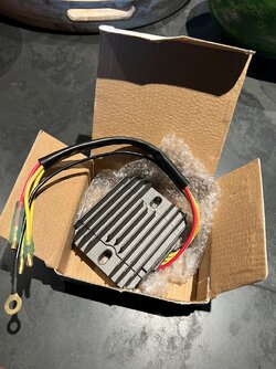
Given can see 5 wires, there is no external sense wire connection. The Black/White wire, ring terminal in best practice attached to the battery negative terminal direct or worst case the high current strap going to frame ( yuk ). Should be a quick lash up Paul, your a bit handy with electrical tools now, a smile here. j
- Location
- Calgary, Alberta, Canada
Hi AndySo Paul’s RR may still be ok? If the sensing input is connected?
Great question, got me thinking.
Starting from basic principles, as I don’t know what I am doing, I researched why some r/r’s have a “sense wire” and others don’t.
The r/r I borrowed from the RGS to try on the 1200 works fine, but I don’t think I made it clear that the r/r from the RGS does NOT have a sense wire. I did not understand the significance of the sense wire when I posted.
If I understand what a “sense wire” does on a r/r so equipped it reads voltage from the circuit through the ignition switch. If the ignition switch circuit is crusty and corroded, the sense wire can get inaccurate information and using faulty information direct the regulator to allow higher voltage. If the sense wire is not properly connected at all, as seems to have been the case with my bike from my own ignorance, then the voltage resulting will be much higher than necessary.
I think the real test of whether the r/r from the 1200 that was regulating a very high voltage is faulty, or just acting on inaccurate sense wire info or lack thereof, is for me to put it back on the bike and connect the sense wire directly to the positive terminal of the battery and see what voltage output results from the r/r. I will do that this weekend and report back. The entire charging fiasco could easily just be my ignorance of the function of a sense wire and how it needed to be connected, we’ll see.
The positive in all of this ( no pun intended) is that I have learned something about regulator rectifiers and 12 volt motorcycle wiring generally.

The Sock
Hero member
- Location
- London, England
Jon may be getting nervous, given the rate you're getting to grips with electrickery, Paul.

1200ts
Hero member
- Location
- USA - Riverside CA
The best option for a RR is a Shindengen FH012AA as fitted to many bikes and very commonly to the Yamaha R1. It is a FET regulator rated for a 600 watt alternator and on the feeble output of a Laverda alternator, does not even get warm. I get them used off Ebay for little money as so many of these bikes are crashed that there is no shortage of them. Be very careful of buying a new one as most are Chinese copies that don't last long. All the new ones I have seen on Amazon or Ebay are fake copies. If the back of the RR does not have an aluminum heat sink plate but is epoxy, it is a Chinese copy. The FH012AA was replaced by the FH015AA and now Shindengen makes the FH020AA. All will work.
This company sells new ones but I always buy them used. https://roadstercycle.com
This company sells new ones but I always buy them used. https://roadstercycle.com
Last edited:

Rob
Hero member
- Location
- Midlands, UK
Just be aware that the space required for the FH020 - and its connectors - means this mod won't be quick or easy on a RGS at least
- Location
- Calgary, Alberta, Canada
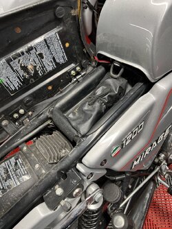
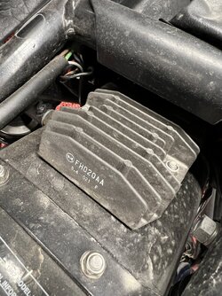
This is where I mounted the Shindegen MOSFET on my 82 1200 TS Mirage. It is quite a bit larger and has larger connectors. I can find space on the other Laverda’s, no problem. I have a “Guaranteed Authentic” Shindegen FA 20 coming from the same eBay vendor that I got the previous one from. The listing shows thousands sold and 5 star ratings.
The earlier tip to check the heat sink for authenticity sounds like a good one, will look and report back when the new Shindegen arrives.
Am also going to retry the r/r I took off the 79 1200 for overvolatge. I found some YouTube videos on hos to test a regulator rectifier with a multi meter and it passes all those tests, will be interesting to see if all this fuss has arisen from my own ignorance about what a sense wire is and does, how to connect it,e tc., or water the problem has arisen from the fire suppressant foam that compromised so much of the electrics on this bike.
The earlier tip to check the heat sink for authenticity sounds like a good one, will look and report back when the new Shindegen arrives.
Am also going to retry the r/r I took off the 79 1200 for overvolatge. I found some YouTube videos on hos to test a regulator rectifier with a multi meter and it passes all those tests, will be interesting to see if all this fuss has arisen from my own ignorance about what a sense wire is and does, how to connect it,e tc., or water the problem has arisen from the fire suppressant foam that compromised so much of the electrics on this bike.
Attachments
The lengthy topic on Robs alternator issues has sections on how to test the RR insitu motor running, Paul,. Mixture of using AC and DC settings on the DMM, even using the DMM on AC settings though referencing ( black lead of the DMM ) on the DC side of the RR. Basic tests on yt are just that, testing only the diode pack and a possible shorted SCR on the regulator devices post 6 pulse diode pack. Is useful though not a complete test of the RR, yt clips. Not sure of the link to Robs posting, perhaps others can post the url here. j
Rob
Hero member
- Location
- Midlands, UK
https://laverdaforum.com/xf/threads/103058/Not sure of the link to Robs posting, perhaps others can post the url
... towards the end of the thread, maybe the last couple of pages