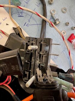
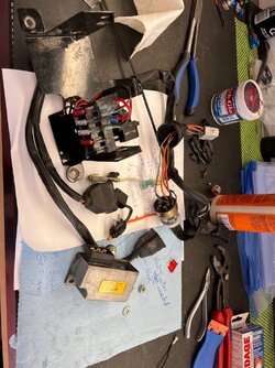
when you are your own dreaded previous owner

I always advise people not to rely too much on wire colours. Who knows what's been done to the bike since it left the factory around 40 years ago?

Always check the simple things first, like fuses. You don't have to be an electrickery genius to do that. :)

You say have +12V battery power to the two 25A fuses (one feeding red to the ignition switch, the other white to the regulator). But if you don't have +12V at the other side of the red fuse, so my immediate assumption would be that the fuse is blown. That could be all that's wrong with the bike.

I assume that you would have checked the fuses before you started pulling the bike's wiring apart, so I'm also assuming it isn't blown. Sometimes fuses can look OK but still be cactus. I always check them for electrical continuity. If the fuse has electrical continuity, then something else is not making contact in the fuse box area. Maybe dirty fuse connections, or dodgy spade connector on either side of the fuse box?

You refer to the "aftermarket fuse box". The usual aftermarket type is one that uses the coloured blade type fuses, with 6mm male spade terminals for wiring connections on each side of the fuse box, so I'm guessing that's what you've got. They're generally more reliable than the ceramic "bullet" type fuse holders that the Laverda factory used, but the spade connectors either side of the fuse box can occasionally fail to make contact. I've had that happen myself. I think the female spade connectors are affected by vibration and heat and tend to get loose after a while. If the bike has been sitting unused, there could also be some surface corrosion (verdigris) that's interrupting the contact. Just pull each female connector off and give it a squeeze with a pair of pliers to make it a tighter fit on the male spade terminal, then replace it. Even if there's some mild corrosion, the tighter fitting terminal will gouge through it.

Once you've fixed the discontinuity in the fuse box. That should then provide +12V at the ignition switch and hopefully all will be well. But since you've already removed the ignition switch and have found broken wires, you may as well check it out "while you're at it".

It's still possible that the key switch isn't working properly, so I'd suggest that you start by confirming the functions of the switch. At least then you know what it does when you turn the key, and whether it's doing what it should.

It's a pretty simple switch. Having told you to not pay attention to wire colours, let's take a leap of faith and assume they're factory original, and refer to the terminals by their wire colours. You know how to test for continuity between switch terminals.

When it's in the OFF position, none of the switch terminals is connected to any other.
In position 1, orange and red are connected. And separately, brown and grey are connected (these two switch functions are not connected to each other).
In position 2, red and brown are connected.

Laverda convention is that red is the power supply from the battery (via the fuse box that isn't working); orange is the switched 12V power supply to ignition (via the kill switch), brown is the parking light circuit; grey enables the headlights because the headlight is separated from the parking light circuit. There should be an orange and black wire somewhere to provide switched 12V feed from the ignition switch back to the fuse box to power other electrical systems like lights, horn, etc. I don't see an orange and black wire, but that connection happens at the other side of that multi-pin connector for the ignition switch (you don't show the other side of that connector block in your photos).

As for the two black wires soldered to the Ignition switch, I'd guess that neither are original. They've most likely been added by an owner at some point in the bike's history. Perhaps that accounts for the poor solder joints that have broken off.

The black wire that's connected to the same terminal as the orange is a switched +12V feed for something. I'd guess an accessory of some sort, like heated handgrips or a voltmeter.

The other black wire (connected to the same terminal as the red wire) is a permanently powered +12V feed to something. Perhaps it powers another accessory that you want to be powered up when the ignition is off. Maybe a 12V outlet for phone charging, or a plug to connect a battery charger to the bike.

If you have accessories that aren't working, those broken black wires may be the answer.
removed all the old Bosch stuff and related wiring. Aftermarket fuse box corroded, and no battery power to the fuse terminal.

removed everything made all new proper connections, fresh direct power wire from battery positive to fuse box terminal. Now have lights, engine cranks over on the starter button.

I pulled a plug, grounded it, turned engine over on starter button, I do not appear to have spark. Is a John Wilson IIS box, my memory is that it has some sort of test switch setting. The switch on the box is set to "3". Rotated the switch selector with a small screwdriver, nothing.....

In my garage fire I lost most of my motorcycle documentation, manuals, instructions, etc.. So no documentation to refer to to trouble shoot the IIS. There is a tiny little power wire from the IIS box to the positive terminal on the battery. I have not started checking the ignition box wiring, will have to pull it all out and take it apart.

I am hoping John comes along to describe how/where I check to be sure the IIS box is properly getting ignition power and how to troubleshoot. I am sure the box is fine, it must be in the wiring. Is there a test setting on the box?
 

Attachments

  • 1200 ignition 6.jpg
    1200 ignition 6.jpg
    162.5 KB · Views: 45
  • 1200 ignition 7.jpg
    1200 ignition 7.jpg
    172.1 KB · Views: 44
  • 1200 ignition 8.jpg
    1200 ignition 8.jpg
    182.7 KB · Views: 44
There is but I cannot remember what setting on the switch it is. It does a little show when selected firing all plugs at 1000rpm differences gradually getting faster and faster. The plugs need to be out and earthed on the engine. I just looked it up its position F. Do you have any lights on the box working? Best I leave the rest to the horse's mouth, luckily I was relatively local and John fitted mine as wires and me don't get on.
 
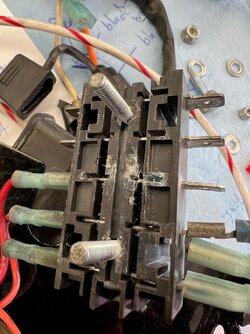
Blimey. That's a lot of corrosion on the brass parts of the fuse box. Do you live in a particularly corrosive environment? You normally only see that sort of corrosion on bikes and cars that live in a salty marine atmosphere near the coast. Are the insulators on the female spade terminals supposed to be that greenish colour, or is that verdigris? I reckon the simplest way to fix them is to snip them off the wires and crimp some new ones on, provided you have enough length of wire.

You have more patience with cleaning than me. I think I would have thrown that fuse box in the bin and fitted a new one rather than trying to clean all that corrosion muck off. They're only about $20. I'd pay that much to avoid cleaning it.

That naked fuse must have been pretty well corroded in place if the plastic cover pulled off leaving the fuse stuck in the holder! Never seen that before.

You're making good progress. I don't know anything about IIS ignitions, but I'm sure John will be along shortly.

Just one other question: If the bike has IIS ignition, what are those Bosch BTZ boxes doing in there?
 
See post on rearset aluminium repair Paul, high temp on aluminium has caveat attached... well you know what that means, a grin here.... you may tack the broken hardened screw body, with a very fine TIG electrode on low current.... even then...shudder... is there not a park eroder person near you?? j
I've done that many times to anneal snapped not so "easy outs" snapped off in snapped off fasteners, I then use a carbide slot drill to remove both easy out and fastener remnants on a cnc mill
 
My first thought was about cleaning fluids - the alkaline type can produce such a corrsion effect in quick order if the are not washed off afer doing their cleaning thing.
 
I was just using existing bits for troubleshooting. I will be buying and using a brand new fuse box of some sort, all new wiring connectors, etc.. I also have a brand new OEM wiring harness I am considering using.

For the corrosion, I did the wiring likely 20 years ago, I doubt the bike has been washed more than 10 times in total in 20 years, although it has been ridden in the rain relatively frequently. I typically use a waterless cleaning spray, and a silicone spray. To be honest it was fairly grungy under the seat, hadn’t been cleaned in a long time, likely at least 3 or 4 years or more.

Whatever the cause, I need to fix this correctly, shopping fuse boxes today, and going to drop by the electrical supply wholesale place for connectors etc.
 
Am here Paul, see the posts very early in a day 4am onwards, get called away from time to time, in a day, do check in during a day if able.

There is no direct "power" from the TA box to the battery positive, there is however a 24awg wire, black in colour, that is the return power to the battery negative, being bold it would seem or possibly this black wire is on the wrong terminal at the battery. There should be a display of switch position number in the window, i would return to switch position 2, when the black wire is connected to the battery negative terminal. Await your first instance of reply, before proceeding with diagnostics Paul.

As for main fuse, up stream of main fuse block carrier, i used the redundent starter solenoid from Kwaka 250's with onboard main fuse and integral rubber holder for spare fuse. Very compact and not a failure prone item, correlates to plenty at local wrecker/recyclers for little money HTH j
 
Last edited:
Ok, Paul. No damage will result from the mis connection. Am here at your disposal.

The iis test positions; there are two, "F" Fires all plugs from 1000rpm to 10,000rpm in a chronometric progression, endless cycle. "E" for encoder tests the crank shaft encoder and allows the TDC reference point to be set on the stator plate for 180/750/Monty, or the later 120 pcb encoder only.

The F test allows diagnostic process for intermittent ignition issues without the need to have the engine running, very versatile in many ways. j.
 
thanks again, John! In my limited defense, that tiny wire and connector has (now had) a bright red insulator on it, which I mistook to mean positive. Now cut off, new black shrink wrap on new connector, plus a label for "ignition negative to battery".

stopped at electrical wholesaler on the way home from work, picked up bags and bags of new pro quality connectors, more shrink wrap tubing in various sizes, and a new fuse block. All cheapo connectors are being replaced on the entire motorcycle, and everything is being labeled as I go.

so John, the bike has been running on ignition switch box position 3. I saw in your earlier post in this thread you were suggesting I set the ignition to position 2? What is the difference between 2 and 3?
 
Ok Paul, black wire with red crimp collar, your a betting man perhaps, bet on the black, or bet on the red.... winner takes all, see how it goes. Red is for 1,5m/m crimp lugs, Blue for 2,5m/m crimp lugs and 6m/m for Yellow crimp lugs, industry colour codes and standard in many countries. If you use a blue connector on 1,5m/m wire it will pull off after crimping.

Switch map selection; Simplified the number of ignition maps or curves, had 10 to make use of, since nearly all iis went over seas, mostly to England. Too many curves to manage by remote support, basic is switch 2, easy curve with low probability of over advance for range of fuels. Curve/switch 3 is aggressive, intended for tuned motors, for the most part CR big inlet valve/smaller exhaust valve. Maximum advance is 36DBTDC and well early in the rev range, about 3500 to 4000 or so, depends on crank velocity moment.

The iis software only times a portion of the crank cycle, 40 degrees only so the maps react quickly to big throttle handfuls, hope that helps, if you had no pinking go for switch 3, depends also on the base stator plate position, if you retard from TDC all curves will retard, pre tdc all curves will be advanced. j
 
John, I have just bought an engine from Caustic Chris with one of your early ignition/alternator set-ups fitted but I don't have the box of tricks to go with it. Is there an answer to this problem?
 
John, I have just bought an engine from Caustic Chris with one of your early ignition/alternator set-ups fitted but I don't have the box of tricks to go with it. Is there an answer to this problem?
Take this to private message, would be best. j
 
Ok Paul, black wire with red crimp collar, your a betting man perhaps, bet on the black, or bet on the red.... winner takes all, see how it goes. Red is for 1,5m/m crimp lugs, Blue for 2,5m/m crimp lugs and 6m/m for Yellow crimp lugs, industry colour codes and standard in many countries. If you use a blue connector on 1,5m/m wire it will pull off after crimping.

Switch map selection; Simplified the number of ignition maps or curves, had 10 to make use of, since nearly all iis went over seas, mostly to England. Too many curves to manage by remote support, basic is switch 2, easy curve with low probability of over advance for range of fuels. Curve/switch 3 is aggressive, intended for tuned motors, for the most part CR big inlet valve/smaller exhaust valve. Maximum advance is 36DBTDC and well early in the rev range, about 3500 to 4000 or so, depends on crank velocity moment.

The iis software only times a portion of the crank cycle, 40 degrees only so the maps react quickly to big throttle handfuls, hope that helps, if you had no pinking go for switch 3, depends also on the base stator plate position, if you retard from TDC all curves will retard, pre tdc all curves will be advanced. j
thanks John!!!!
 
Paul your corrosion may come from your heated garage in the winter. I have to run a dehumidifier in mine as it is so tightly sealed that in the cold weather the humidity gets really high from ice and snow melting off the car, snowblower etc.
 
Paul your corrosion may come from your heated garage in the winter. I have to run a dehumidifier in mine as it is so tightly sealed that in the cold weather the humidity gets really high from ice and snow melting off the car, snowblower etc.
Hi Henry

as I get deeper into the wiring I am finding more corrosion issues. It just hit me. When the 1990 Bentley Turbo R caught fire in my garage a couple of years ago in early winter and gutted the garage to a bare shell, all the motorcycles were in the garage and got saturated with fire suppressant foam before they were hauled out while the fire was still raging. Then the motorcycles got moved to unheated storage and spent the winter months without being able to be cleaned as it was too cold to wash them. They still had the fire suppresant foam remnants and all the heavy soot on them when I was finally able to wash them in the spring. I am now guessing that the corrosion in the fuse panel and connectors etc may have resulted from the fire and the fire suppression foam used by the fire department?

anyway, whatever the cause, I am just replacing and renewing everything in the wiring harness and replacing the fuse block etc.. "While I am at it" I am considering finishing rebuilding the Mikuni RS 36 carbs and re fitting them to this bike, it has been running Dellorto's the past few years, long enough all the fuel hose is petrified again and the inlet rubbers are looking questionable.....
 
This evaluation of AFFF (Aqueous Film Forming Foam) comes from the aircraft industry.

AFFF can be extremely damaging to aircraft and aircraft components.
Both AFFF and high-ex have essentially the same pH as their water source but can be extremely corrosive to hardware line circuit boards and similar as the foam tends to stay on the board rather than run off.
One major brake pad manufacturer will not warranty brake pads if they come in contact with any foam solution, either AFFF or high-ex.
Foam exposure warrants thorough aircraft inspection and possibly market devaluation.


I think it's reasonable to expect similar effects on motor vehicles, including motorcycles.
 
I have seen TV shows where they are reluctant to foam fires on race tracks because of how hard removing it is. Actually, I think that was Powder Extinguishers. Dammed if you do dammed if you don't. I think on car fires the local Fireys go to they use their small truck hose and the water they carry in their truck, Legs what happens in South Oz? BTW there was a recent big financial settlement from the Oz Federal Government to farmers bordering one of the local Air Force air stips because that foam had entered the farm livestock DNA. I don't remember widespread numbers of plane crashes there that needed heaps of foam so maybe it happened just from practice use.
 
Back
Top