wanted - moto giro bike

From TDC, intake valve to open in first 180 degrees, second 180 degrees both valves closed, third 180 degrees both valves closed, final stroke exhaust valve opens last 180 degrees, from 540 - 720 degrees.

Yes, you definitely sound confused. Inlet should open some time before TDC, not in the first 180° after TDC. The first event after TDC on the power stroke is the exhaust valve opening.

If you start on the power stroke: Plug fires a bit before TDC, then nothing happens with the valves until a bit before BDC when the exhaust valve opens. It all depends on your cam profile, but a typical figure might be around 45° BBDC or 135° ATDC. As the cycle continues past BDC and the piston rises, it gets most of the way to the top when the inlet valve opens, perhaps around 20° BTDC. Once you're past TDC, the exhaust valve closes. Let's say this happens at 20° ATDC. That bit between inlet opening and exhaust closing is the overlap. Normally, the middle of the overlap period is roughly centred around TDC on the non-spark, or "breathing" stroke. Or perhaps with a bit more of the overlap on the ATDC side.

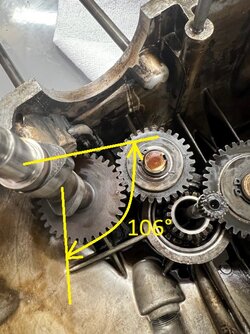
It's a single camshaft, so the relationship between inlet and exhaust timing is fixed. Looking at the photo of the camshaft here: https://www.laverdaforum.com/xf/attachments/61114/
the lobes on the camshaft will be separated by about 120° plus or minus around 20. It's that 120° "V" between the lobes on the camshaft where the overlap happens.

A good starting point would be to set the piston at TDC and then engage the cam gear so both tappets have about the same lift on the non-spark stroke. If the tooth pitch doesn't let you get it centred on TDC, retard the cam until the next available tooth (move the cam gear opposite to the direction of rotation). That'll bias the overlap after TDC. Your camshaft gear looks like it has about 36 teeth. If that's the case, then shifting one tooth either way will change the timing by 20° at the crank. That's quite a big jump, so hopefully the correct spot will make itself obvious.

I don't recall how the ignition timing is arranged so you might have to assemble the points to figure out which stroke is which.

Having done all of that, check the exhaust opening and inlet closing positions. They should be roughly the same distance either side of BDC (around 40-60°?) but not on the same stroke - there's no overlap there.

All of the above figures are just examples. Your camshaft maybe wildly different. To get an idea of what your cams are doing, you could have a close look at the camshaft itself. Measure the offset between exhaust and inlet cam lobes. Once it's in the engine with the cam followers installed, use a degree wheel to get an idea of the duration that each valve is open. You can stick all those figures in a spreadsheet and play around with the numbers until they look something like the numbers you've measured. Then make an educated guess as to where TDC fits into that table of numbers.

I've prepared a little spreadsheet for you. Just play around with the numbers in column 2 until they resemble what your cam actually does.
I've included a calculation of the cam lobe offset that you can check against your camshaft.
 

Attachments

Thanks, Cam!! if TDC is supposed to be in the middle of intake and exhaust overlap, then cam to crank timing must be out, as the exhaust tappet is completely closed by TDC at the end of the exhaust stroke. Thanks for all the info and spreadsheet. After midnight here, so will get back to this tommorrow after I go pick up the second dial indicator. I charge ahead on the basis that there is no such thing as a stupid question, and that I do not mind demonstrating my ignorance, clearly on display here.........
 
I'm quite confident that cam timing is rather conservative, ie, more-or-less symmetrical around TDC, give or take 5-10° (probably less than what a tooth at the crank amounts to). At a monstrous 53hp/l, there may not be much overlap at all, maybe none, but that would be rather unusual for the era. I'd start by setting the crank at TDC and the cam with ex. lobe closing/in. lobe opening slap-bang in the middle. When at compression TDC, the lobes should be equally symmetric, only opposite to the overlap stroke. Rest the pushrods on the followers, these can give a clearer indication of what's going on down at the cam. Aim for the same height at both rods at TDC, forget the dial indicators, etc. Actually knowing when the valves open or close isn't going to get you any further, the relationship between them is fixed, as Cam has pointed out.

If the ignition points are driven off the cam, it may be worthwhile to check the fitment of the points cam and base plate. Both should fit within the adjustment range provided by the base plate, easy enough to find out with a degree wheel if ignition timing is known (I'd assume somewhere around 35-40° BTDC). If the points cannot be arranged to be within the adjustment range, the cam timing is out, easy peasy... ;)

piet
 
I'm quite confident that cam timing is rather conservative, ie, more-or-less symmetrical around TDC, give or take 5-10° (probably less than what a tooth at the crank amounts to). At a monstrous 53hp/l, there may not be much overlap at all, maybe none, but that would be rather unusual for the era. I'd start by setting the crank at TDC and the cam with ex. lobe closing/in. lobe opening slap-bang in the middle. When at compression TDC, the lobes should be equally symmetric, only opposite to the overlap stroke. Rest the pushrods on the followers, these can give a clearer indication of what's going on down at the cam. Aim for the same height at both rods at TDC, forget the dial indicators, etc. Actually knowing when the valves open or close isn't going to get you any further, the relationship between them is fixed, as Cam has pointed out.

If the ignition points are driven off the cam, it may be worthwhile to check the fitment of the points cam and base plate. Both should fit within the adjustment range provided by the base plate, easy enough to find out with a degree wheel if ignition timing is known (I'd assume somewhere around 35-40° BTDC). If the points cannot be arranged to be within the adjustment range, the cam timing is out, easy peasy... ;)

piet
That is exactly what I was trying to say with resting something flat on the cam lobes at TDC on overlap stroke, Paul, having it sit flat to show that both lobes were even either side. Doing as Piet says will have the same effect. Very simple.
 
Are you interested in my LB1 Custom? it's all prepared; it runs, but it needs neu jets. It has swiss papers and it's in my garage in switzerland. This was the best 125 at the time; the motor was not from Zündapp but from Laverda itself.
Regards Romeo
 
Are you interested in my LB1 Custom? it's all prepared; it runs, but it needs neu jets. It has swiss papers and it's in my garage in switzerland. This was the best 125 at the time; the motor was not from Zündapp but from Laverda itself.
Regards Romeo
Hi Romeo

thank you for the suggestion. My purpose for a small displacement motorcycle is to run the Moto Giro. The rules here are 1969 and prior, in a couple of classes, less than 150 cc, less than 250 cc. Your Laverda 125 Custom would dominate the field at 17 liquid cooled 2 stroke horses, but as the 125 LB was 1982 or newer, I think, it would not be permitted to compete, sadly.

the reason I bought a 1957 is that some of the classes in other Moto Giro events elsewhere in the world restrict entries in some classes to 1957 and prior, or so I am told. Going to run locally first and see how I fare. If and when I get the cam timing figured out, thanks for the help, I did not understand what you were referring to originally. Now through my own ignorance I have to split the cases to get at the cam and cam gears and make the change.

Romeo and Piet, with the cam inside the engine case half, I am not seeing any realistic way to measure the lobes as being equal to each other at TDC without closing the case halves up again, which frankly is a bit of a chore and not somethign I want to do repeatedly, need to get it right this time somehow......

Paul LeClair
 
Hi Romeo

thank you for the suggestion. My purpose for a small displacement motorcycle is to run the Moto Giro. The rules here are 1969 and prior, in a couple of classes, less than 150 cc, less than 250 cc. Your Laverda 125 Custom would dominate the field at 17 liquid cooled 2 stroke horses, but as the 125 LB was 1982 or newer, I think, it would not be permitted to compete, sadly.

the reason I bought a 1957 is that some of the classes in other Moto Giro events elsewhere in the world restrict entries in some classes to 1957 and prior, or so I am told. Going to run locally first and see how I fare. If and when I get the cam timing figured out, thanks for the help, I did not understand what you were referring to originally. Now through my own ignorance I have to split the cases to get at the cam and cam gears and make the change.

Romeo and Piet, with the cam inside the engine case half, I am not seeing any realistic way to measure the lobes as being equal to each other at TDC without closing the case halves up again, which frankly is a bit of a chore and not somethign I want to do repeatedly, need to get it right this time somehow......

Paul LeClair
Isn't there an intermediate gear? If that's the case, crank at TDC, cam midway and slip the intermediate gear on. Or if possible, slip the cam on with the crank at TDC and cam lobes either side of vertical?


Paul
 
Check which way engine and cam turn.

Paul
both crank and cam turn forward, towards the front wheel. I am taking a break from cam timing. Frustrating rather than fun, not understanding..... Will leave it for a while and come back at it fresh in a while. Cylinder barrel, new oversize piston, and the head, are with the machinist, and the 12 volt conversion and digital ignition are not here yet from Vape in Chechia. Can't do anything more with the motor right now anyway. Will let cam tining concepts percolate in my head for a while before gettign abck to the cam.

The custom made polished spokes from Central Wheel in the UK are supposed to be here in the next 48 hours, going to turn my attention to wheel building when the spokes get here.
 
both crank and cam turn forward ...
OK, so there must be an idler gear between them. Yes indeed. I just found a photo of the cam gearing way back on page 9 of this thread. It looks like the tooth numbers are 17/34 with 29 teeth on the idler gear. Having prime numbers for the teeth on the idler and crank gears is good design because it provides a hunting tooth gear system to keep tooth wear even (gears engage different teeth each revolution). Obviously the camshaft gear will always have an even number of teeth.

17 teeth on the crank timing gear means you can only change the timing in increments of 360/17 = 21.17° of crank rotation (the idler gear doesn't affect the indexing increments). That means it should be pretty obvious which is the right timing. If you're off by a tooth either way it'll be well away from the middle overlap at TDC that we referred to earlier.
 
Last edited:
You sure the idler can't be used in setting cam timing? If you moved it one tooth fwd or back it would be altering the diff b/w crank and cam gear by 360/29. As long as either the crank gear or the cam gear are still engaged with the idler, it will alter it by the increments of the idler, not the crank or cam gear. Or have I got it wrong - I didn't look at the pic.
 
OK Paul. I've had a look at your engine photos. The tappets are in front of the cylinder and parallel with the cylinder bore. So that makes setting it up pretty easy.

It looks as if the crankshaft goes in last if you're assembling everything in the timing side crankcase half, so I guess the order of assembly will go something like this:

1. Put the timing idler gear on its stub shaft and fit the circlip.
2. Insert the camshaft so both tappets are lifted by the same amount. Put a straight edge across the tops of the tappets to check that they're equal heights.
3. Without moving the camshaft, put the crankshaft in as close to TDC as you can get it. If the timing gear doesn't engage at TDC, rotate the crank forward until it drops into the next available tooth.

That's pretty much all there is to it.

I don't remember where your ignition timing comes from, but I don't think you need to worry about which stroke the crank is on. If the ignition is is on the end of the crankshaft, it fires every revolution anyway. If it's on the camshaft, it should still be OK because you're not changing the relative positions of the valve cams and points cam.

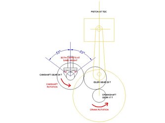
I've done a drawing for you. I estimated the cam lobe separation at 100° from your photos. Edit: now known to be 106°

cam lobe separation.jpgCam timing.jpg
 
Last edited:
A lot for me to absorb. I am still stuck on the equal height tappet thing. Yes there is an intermediate gear. The cam can be removed and installed with the crank in place. I put the crank at TDC then slotted the cam into place. Nearly midnight here and U start a couple of days long trial in the morning. Likely can’t get back to the Gilera motor until later in the week. Thanks so much for the help and info!!!!!!
 
Hi Cam, and all

I got a really helpful email off forum from a self described forum lurker who referred me to an online Gilera manual that has basic details of cam timing for the 150 single motor. I have it printed out, scanned, and partially translated from Italian. Don't know if you are willing, but I am going to message the scan to you.

Considerations include that the degrees specified are based on a particular rocker clearance, etc., but i think I can figure out how to accommodate that even working directly from the tappets riding directly on the cam.

the real problem is that while the intake tappet is easy to check as it is in the main case half, but checking the exhaust tappet is impossible with the case halves separated. I am going to have to figure out how many teeth to move the cam, and in which direction, before I split the case again.

Roughly translated, and subject to the particular rocker clearance required on 0.30 mm, the cam timing appears to be as follows:

Intake start 32 degrees before P.M.S. is that TDC?)

Intake end 64 degrees after P.M. I ( is that BDC???)

Exhaust start 64 degrees before P.M.I

Exhaust end 32 degrees after P.M.S.
 
Checking cam timing using degrees measured when a valve opens for a given tappet/rocker clearance is very difficult because a minute diff in clearance can translate into many degrees. And you can ignore the exhaust timing figures because exhaust lobe position is fixed relative to intake. PMS = punto morto superiore (TDC), PMI = punto morto inferiore (BDC). Before PMS is BTDC, after PMI is ABDC.
 
So lobe centres are 106 degrees (is that right?) for both intake (ATDC) and exhaust (BTDC) so you should be able to measure with a dial indicator on the tappet of whichever valve you choose. If its close then you're good to go, you don't need to measure the other valve.. No?
Stu
 
Just to bring other readers up to date, Paul sent me the manual info on the Gilera cam timing, which is answers all the questions about cam timing.

It gives the precise cam timing (with valve clearance set at 0.30mm).
The reason for opening up the clearances for measuring purposes is to get past the quietening ramps on the cam lobes.

Inlet opens 32° BTDC
inlet closes 64° ABDC
exhaust opens 64° BBDC
exhaust closed 32° ATDC

The Italian acronyms PMS and PMI refer to TDC and BDC respectively (Punto Morto Superiore and Punto Morto Inferiore). Prima and dopo are before and after. Inizio and fine are start and finish. Although we English speakers tend to say open and close when talking about valve timing. So Paul's interpretation there is correct.

There's 64° of overlap, so it's roughly equivalent to a Laverda 750 GT in its state of tune. It's not a screamer but should be a nice tractable engine with a little bit of top end.

The manual also says normal running valve clearances are 0.10 mm inlet and 0.15 exhaust on a cold engine.

It also confirms that the tappets have flat faces "punteri a piatello".

So, the speculation by Piet and myself that the overlap is centred around TDC is absolutely spot on. Exactly 32° before and after.

The diagram I posted earlier is also correct except my estimation of 100° as the angle between the cam lobes was a little off. It's actually 106°. I've edited the diagrams to correct that slight error. If Paul uses that diagram as an assembly guide, the cam timing will be correct.

It's nice to get to the bottom of a mystery and finally have all the answers :)
 
Last edited:
Back
Top