Weird

Well Andy, what's the likely hood of 2 fuck stators!!. The one I brought even though 2nd hand looks brand new.
I'll change the RR tomorrow and start again
Also I'll disconnect the RR from stator and recheck voltage output. Was getting 15v at idle and 60v at 4000. Both stators tested the same results and all 3 combinations were pretty even
 
Tough one all right, all the same Rob, your working at a technical level few would carry off, you ought to be well proud of yourself, your quite "The Man with DMM".... Doff's me Arai...

Best practice is to make certain assessments or assumptions, for a moment, my thoughts are turning to the failed brand new RR? The fault or combined faults come and go, seemingly without a pattern or similar.

When you located a low volts on U phase, and then reversed the connection with W and the low volts stayed with U connection, then as you called it Rob, the fault is downstream of the stator, caveat...would also swap U with V and retest the measurements, looking for the low volts to move position on the terminal block ( could you imagine doing all this with a plastic connector system ).

One advantage of all this, there is not a lot of parts to contend with, parts have been swapped and the fault remains, then you look closely at the common parts or sections that remain or common when the major parts are swapped. Not inclined to believe your have 2 faulty stators, and or RR's. Though i did have a fault once where 3 brand new parts were all faulty as the same as original part, conviction had a new meaning installing an electronic part for the 4th time in a row, and it worked on the 4th part. If that helps, doubt it today Rob, wry smile here....more soon...tea calls me...j
 
So what are we thinking? Another stator?
That slow voltage change seen previously could be an indication of intermittent shorts between turns?
As you say Andy, shorted turns have peculiar properties and almost impossible to detect, unless test equipment is at hand. The smoking vacuum cleaner motor or electric drill with massive sparking on the armature commutator is a clue, no test equipment required then, a grin here. Experience and old test equipment like a "growler" ( one for the trade out there ) can assist. Shorted turn can exhibit different modes, when the field or armature is loaded and unloaded. My fear is testing the ND stator here without loading, will stress the interwinding insulation and introduce a new fault or faults in the future at worst. j.
 
Ok will do those test
Just swapped the stator U wire with W
U 0.4 V 4.8 W 4.8
Sort of tells me the problem is down stream.

+ probe to battery +
DC U 13 V 8.7 W 8.5
AC U 0.68 V 7.5 W 7.5
This caught my eye, the last bracket set of readings, battery positive, thinking out loud, reads that one of the U phase diodes has gone short circuit, ie high volts on DC test, and then low volts for AC test only on U phase, needs me pot of tea and ponder.
1663450226953.png
 
Morning John, 2 hours behind you or is it 3 yet? just sitting down with my first cup of tea, another 2 and I'll be ready for a visit to the shed again. Tea always help.
The RR currently fitted is the original SH530. Will swap with the replacement SH530. Have already determined that the new one I got from Red is faulty as nothing came out of it and when I did the diode test it showed an issue where as the 2 SH530s tested with the exact same results.
So first I will disconnect the stator and retest AC output as well as the ohmes test. Then I'll swap RRs and go from there. Also need to reroute the stator wires to give me more length after cutting back spades, deutsch pins and striping for the terminal block there isn't much free play left.
Also will swap U with V before changing anything. What has come out of this is I'm slightly more knowledgeable of the DMM.
 
Tea, 2-3 pots here for me to cold crank start.... am alert just not ready for engaging a day manually....

The Redax RR, was more interested in what took it out, as it worked initially.

Yes good move, swap Stator U to Stator V position, transpose. Retest as per previous.

Not yet comfortable in pointing a bone at the stator, have you tried pointing ex shaman tools of trade at the fault, wore my magic wand out, hard to find working ones these days, the chinese ones look ok yet dont seem to work... must be me....j
 
No shaman tools pointed yet, only threats of selling it if it doesn't behave. Even the Budda in the dash isn't looking out for me though I have earned much "Boon" [merit} having paid to build a sala [temple] on land my wife brought and gave to the monks in Thailand.
Am off to Perth next weekend to catch a flight to Brissy for the Bellingen Rally and if I have to resort to riding the BM the Motodd is in big trouble.
 
Well John we have lift off
Changed the RR and there were equal readings~ on all those test and climbs to 14.5 a lot quicker than before so I'd say it's all good. Even reconnected the sense wire back into the ign. circuit.
Now the question is why the inconsistent outputs. There was a definite improvement in changing connectors and did see 14.5 though slow to climb. Next morning either nothing or a slow climb to 13.5.
So a big thank you for your input. Maybe one day we'll catch up again and the beer is on me.
Don't suppose your going to Bellingen?
Cheers
Rob
Progress Rob, may it continue. Few aspects that have my attention remaining all the same. None of the battery charge parts and wiring are near to the High Tension ignition parts are they? Especially the HT cable to spark plugs and ignition coils, you have two RR's damaged and no causal factors identified as yet. Reads like diode punch through, which can be traced back to high voltage spikes or back emf sources. You can relax for the moment and i will take over the worry duties.....

As a suggestion and demands allow, write down all the voltage test results now that the charging system is working as designed, give you known good voltage readings for the future, to measure against should trouble re-occur. Perhaps publish the figures in this topic or library, can help correlate the figures if required.
j.
 
nah all the HT stuff is frame mounted above the cam cover.
The RR is mounted onto the carbon fibre elect. box with a rubber spacer behind it just above the engine breather hose.
It is a worry that 2 RRs have failed. When fitted the new one from Red it worked fine initially but 800 kays later it was dead dead. Not sure when it died in those 800 kays. There is the diode test results on all 3 RRs a couple of pages back. Going to retest the RR and compare numbers
 
Last edited:
nah all the HT stuff is frame mounted above the cam cover.
The RR is mounted onto the carbon fibre elect. box with a rubber spacer behind it just above the engine breather hose.
It is a worry that 2 RRs have failed. When fitted the new one from Red it worked fine initially but 800 kays later it was dead dead. Not sure when it died in those 800 kays. There is the diode test results on all 3 RRs a couple of pages back. Going to retest the RR and compare numbers

The basic static DMM diode test is useful, the faults your encountering require a completely different type of test regime, the active in circuit AC DC tests you have done in the last few days, will provide a superior test of RR and Stator in normal on bike operation.

Time to relax all the same, enjoy a lull in the proceedings, there are enough basic figures recorded here. Your AC U V W balanced readings for 1000/1500 rpm and 3000 rpm would be useful all the same.

Ok on HT circuit isolation, the failed RR are a notable issue to identify as yet. j.
 
Diode test to duff RR
Red probe to earth
Black probe to each phase, 2 showed 0.48 and the other -0.002 so that explains it but a couple of weeks ago it checked out OK. Is why I reinstalled it and brought a new stator.
Hopefully they're just duff RRs and not being cooked by something.
The new one from Red isn't a SH530 but wouldn't have thought it would fail so soon.
 
The AC balance readings
@ 1000,1500, 3000,
Connected to RR or disconnected?
1000 to 1500rpm ( where the engine idles is fine ) for one set of readings, then 3000rpm to gauge the rise in UVW AC readings, all connected as normal, RR in circuit, charged battery in circuit, ie as you would ride normally and have a battery on proper float charge. Hope i make sense. j
 
@1000
UV 11.8UW11.8 VW11.8
@2000
UV7.6 UW8.0 VW7.4
@3000
UV7.8 UW8.0 VW7.9
Higher voltage at idle????
There is quite a fluctuation in readings so sort of recorded middle
 
Hey Jon, you seem to have Rob's problem pretty much sorted for now (and I learned some new test modes too), so how about a slight change of tack for a moment?

You may have to switch your brain to idiot mode. Here comes a question from an idiot:

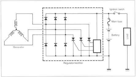
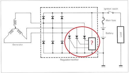
Can you confirm what this bit of circuitry (in the red circle below) does?

I think I have the basics. It appears to be the regulator part of the RR. Those 3 diode-looking things attached to the mysterious box are actually SCR's with their gates being controlled by the mystery box. I'm guessing that if the output voltage to the battery positive goes high, then some little bloke in that mystery box pulls a lever to open the gates on those 3 SCR's, dumping the alternator pulses to ground, or battery negative if you prefer. Or maybe back to another phase winding in the alternator via a negative rectifier diode - buggered if I know where it goes.

Conversely, when output voltage is low. The 3 SCR's are switched off (not conducting) so whatever feeble output the alternator can muster at that stage (if any) all goes to the battery.

But what bit of magic trickery is in the mystery box. I'm guessing it's an IC with a jumble of electronic components that's beyond normal human comprehension. That's why it's represented in the diagram as just an empty box so as not to confuse us idiots. I've taken its emptiness as an invitation to fill it with a helpful question mark. Whatever is in there, I presume its purpose is to provide a switching voltage, or not, at the SCR gates. Thereby switching the RR into charging or not charging mode.

One of the reasons I'm in stupid question mode is that I'm wondering if there's a way to get into one of these things and interfere with its inner workings. I presume that would involve dissolving out an epoxy potting compound, if that's even a possibility.

It seems that nobody makes a 3-phase alternator with an output for a charge light. This begs the question as to why not. The type of molestation I had in mind was to provide one. I just want a 3-phase RR that'll actually say whether it's charging the battery or not, like some single-phase ones do. The one on my Ducati for example.

Would it not be possible to use a signal from one of the SCR gates to control a charge indicator lamp? Or would tapping into that connection be equivalent to looking at Schrodinger's cat, and forever fix it in one mode or the other? Or maybe it cycles so fast that it would just make an annoying buzz.

Maybe there's a simple answer. Perhaps the IC box is the same as those used on the single-phase RR's and has an (unused) pin for an indicator light. All it needs is for a wire to be connected to it. I don't suppose you know the identity of the IC that these things use.

Trying to understand all that pnp and npn junction stuff does my head in. I could never get it through my thick skull in the electronics class that I had to do as part of my engineering studies. I think the electronics lecturer gave me a pass mark out of pity, secure in the knowledge that as a mechanical engineer I wouldn't ever need to understand how this stuff works. He set the same low bar for the civic and structural lads too. He was right. The lack of understanding of electronics was never a hindrance in my working life.

RR innards.jpg
 
Indeed Cam, your suspicions are correct suspicions, way better than wrong ones.... wince and a grin. The most complex part of the actual shunting of excess charging current, travels a tortured path back to the balanced alternator phases ( in this case of a drawn Y connected poly phase configuration, if a Delta these outputs would be "Line" outputs ** ). Need a voltage diagram of a 120 degree 3 phase generator to see the instantaneous EMF ( proper name for "voltage" ), when one or more of the SCR's fire into forward conduction, until the gate is triggered, these SCR's are non conducting.

The battery negative output of the RR looks to the control circuit as just another connection, point to point, looking back into the RR, it constitutes a return path of excess charge current back into all three of the lower three rectifier diodes. Dependant on vector EMF on two of the other Phases, how much current is dumped back into the stator windings. Over simplified though gives an idea, or i hope it does.

AC alternator "Charge" lights are in my view, a faked indicator, trying to emulate the old back feed prevention relay on DC generators which when GEN output fell below the battery volts, a clever coil system would operate the gen light from aux contacts, disconnecting the GEN from the battery, apologies if known already. Since there is no "disconnect" relay in our RR's then we use a voltage sense comparator to instigate a high and low volts window circuit, the battery monitor and GEN light pcb i designed had dual comparator "windows" to detect absolute battery voltage. There are solid state current monitors available these days, did obtain a sample of these devices for actual current flow to battery, these devices could sense positive and negative flow of current and read out actual current value with appropriate scaling and readout display. My 1976 929 MAZDA had a real deal moving iron centre zero ampmeter +-50amps and it was excellent, my reg failed and the meter on the dash showed net discharge of the battery.. who cared what the voltage was. Loved it.

Cover more of this as i get a chance Cam, applaud your interest as it happens, we never stop learning...bye for now j.
 
Perhaps to save comprehensive typing on "Gen" light for AC alternator as we use, better path would be a shunt inline with the RR to battery ( T style connection would be best, ie the shunt connected to battery positive, the RR positive output to bike electrical system and that connection to load side of sense shunt ). The latter scheme will indicate nett charge and discharge to the battery.

May resurrect the project, be a simple Red light when discharge, perhaps going to green on charge and no indication a matched battery float terminal voltage to RR output voltage. Maybe i could implement a Bluetooth interface to link with cell phone, you would pull over to see what your cell phone says, "your battery is flat and now you have turned off the motor it will not start again...have a nice day".... perversity.... the essence of modern electronic media.... some call me strange, that seems odd to me... am weird as the topic title says.... hear hear....j
 
@1000
UV 11.8UW11.8 VW11.8
@2000
UV7.6 UW8.0 VW7.4
@3000
UV7.8 UW8.0 VW7.9
Higher voltage at idle????
There is quite a fluctuation in readings so sort of recorded middle
Good man Rob, missed these posts yesterday, lower volts at upper rpm i would believe due to charge current higher and the effect of I squared R losses, most of all the actual magnetic gap between stator and magnetic flywheel doing its job... gets technical....no insult intended. j
 
Back
Top