Hey Jon, you seem to have Rob's problem pretty much sorted for now (and I learned some new test modes too), so how about a slight change of tack for a moment?
You may have to switch your brain to idiot mode. Here comes a question from an idiot:
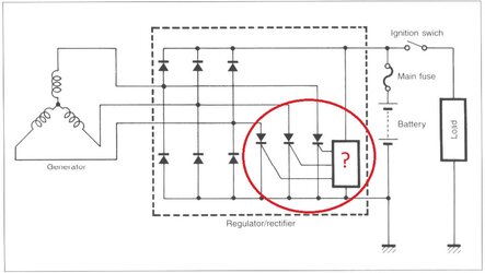
Can you confirm what this bit of circuitry (in the red circle below) does?
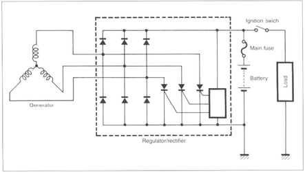
I think I have the basics. It appears to be the regulator part of the RR. Those 3 diode-looking things attached to the mysterious box are actually SCR's with their gates being controlled by the mystery box. I'm guessing that if the output voltage to the battery positive goes high, then some little bloke in that mystery box pulls a lever to open the gates on those 3 SCR's, dumping the alternator pulses to ground, or battery negative if you prefer. Or maybe back to another phase winding in the alternator via a negative rectifier diode - buggered if I know where it goes.
Conversely, when output voltage is low. The 3 SCR's are switched off (not conducting) so whatever feeble output the alternator can muster at that stage (if any) all goes to the battery.
But what bit of magic trickery is in the mystery box. I'm guessing it's an IC with a jumble of electronic components that's beyond normal human comprehension. That's why it's represented in the diagram as just an empty box so as not to confuse us idiots. I've taken its emptiness as an invitation to fill it with a helpful question mark. Whatever is in there, I presume its purpose is to provide a switching voltage, or not, at the SCR gates. Thereby switching the RR into charging or not charging mode.
One of the reasons I'm in stupid question mode is that I'm wondering if there's a way to get into one of these things and interfere with its inner workings. I presume that would involve dissolving out an epoxy potting compound, if that's even a possibility.
It seems that nobody makes a 3-phase alternator with an output for a charge light. This begs the question as to why not. The type of molestation I had in mind was to provide one. I just want a 3-phase RR that'll actually say whether it's charging the battery or not, like some single-phase ones do. The one on my Ducati for example.
Would it not be possible to use a signal from one of the SCR gates to control a charge indicator lamp? Or would tapping into that connection be equivalent to looking at Schrodinger's cat, and forever fix it in one mode or the other? Or maybe it cycles so fast that it would just make an annoying buzz.
Maybe there's a simple answer. Perhaps the IC box is the same as those used on the single-phase RR's and has an (unused) pin for an indicator light. All it needs is for a wire to be connected to it. I don't suppose you know the identity of the IC that these things use.
Trying to understand all that pnp and npn junction stuff does my head in. I could never get it through my thick skull in the electronics class that I had to do as part of my engineering studies. I think the electronics lecturer gave me a pass mark out of pity, secure in the knowledge that as a mechanical engineer I wouldn't ever need to understand how this stuff works. He set the same low bar for the civic and structural lads too. He was right. The lack of understanding of electronics was never a hindrance in my working life.