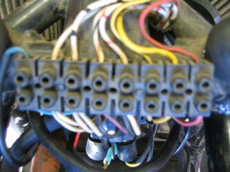
Weird

Mmmmm i should have paid more attention to this quote from Rob of Motodd infamy.... not an insult Rob, quite the opposite... will all the same call it out, the tooling was not fit for purpose or some degree of same. See if the fault settles down after a terminal block is installed in place of Deutsch, there may be copies of proper industrial connection systems. Had to deal with counterfeit output transistors in the buggy repair, turned to smoke as soon as drive was applied, used my reliable supplier after ebay seller fiasco. Element14/Farnell and RS Components ( both UK origins originally ) are my first choice whenever possible, said in order others may benefit as to where a reliable part can be obtained.

"The pins/sockets on the Deutsch connector are pretty tight, used not the proper deutsch crimper but the crimper I brought when I rewired the bike. It's not the top of the wozzer but does a pretty good job of crimping"

There is a reason why certain special devices require costly die forms and tooling. Been reviewing why this fault diagnosis was a lengthy process and what can be improved in the future, photos are the key no question there. j.
 
Yesterday connected stator to RR using a terminal block as John suggested. And a successful outcome. Still think the volts raising @3000 still seems slow but it does get to 14.5 and drops to 14.2 at idle.
Well done to Rob for suggesting the Deutsch plug. Not so impressed with them now!!.
3 RRs, 2 stators and 3 helicoils later. It's been an arduous task and a heap of frustration sorting this out.
So thanks to John for his input even if it was over my head at times and Rob's advice regarding the Deutsch connector.
I learnt stuff which can be useful.
I had a close look at the crimping on the deutsch pins/sockets and they looked pretty good to me. Wires were tight.
After doing some measuring I found that only 5mm of pin actually insert into the socket. and I only got a result when I crimped the socket to an oval but that connection didn't last. Was planning on replacing the other block connectors on the switches with Deutsch but I don't think I'll be doing that now.
Thanks to all who contributed, it was a mind fuck!!!
 
Cam also was not enamoured with the Deutsch connectors. Noted your observation of the contact area for your pins and sockets there Rob, given the actual symptoms it was an open circuit in one or more of the plug/socket arrangement to my mind, notwithstanding the actual steady state current carry specification. Perhaps original specifiction and engineered Deutsch connection systems are valid. Seen similar on the 1992 HD series Mazda here.
 
Yesterday connected stator to RR using a terminal block as John suggested. And a successful outcome. Still think the volts raising @3000 still seems slow but it does get to 14.5 and drops to 14.2 at idle.
Well done to Rob for suggesting the Deutsch plug. Not so impressed with them now!!.
3 RRs, 2 stators and 3 helicoils later. It's been an arduous task and a heap of frustration sorting this out.
So thanks to John for his input even if it was over my head at times and Rob's advice regarding the Deutsch connector.
I learnt stuff which can be useful.
I had a close look at the crimping on the deutsch pins/sockets and they looked pretty good to me. Wires were tight.
After doing some measuring I found that only 5mm of pin actually insert into the socket. and I only got a result when I crimped the socket to an oval but that connection didn't last. Was planning on replacing the other block connectors on the switches with Deutsch but I don't think I'll be doing that now.
Thanks to all who contributed, it was a mind fuck!!!

Damn! No Motodd hitting the market. Just down the road from me too! :D :D
 
I only got a result when I crimped the (Deutsch connector) socket to an oval ...
Yep, a familiar story. I've had to do that with some of the connectors on my Benelli.

Here's my story of why I'm not a fan of Deutsch connectors.

I spent ages chasing a misfire on one of the cylinders on the Benelli triple. I did all the continuity and resistance tests in the workshop manual, none of which revealed a fault. The bike has a coil-over-plug arrangement (which I'm also not a fan of, but that's another story). The stick-type coils have the 2-pin half of a Deutsch connector formed into the plastic top of the coil body that protrudes up out of the spark plug well. The coil primary cables have the 2-socket female half of the Deutsch connector that plugs into the coil. All very neat, tidy and waterproof. You'd think it would be a 100% reliable connection.

After not being able to find a fault, I thought it could have been a dodgy coil even though the primary resistance was OK, so I bought a new set of coils at great expense. But no joy with the new coils. The misfire remained. Back to the drawing board. I repeated the list of tests in the manual: Coil primary resistance OK. Continuity test of primary circuit from ECU plug to coil Deutsch plug was OK. I even borrowed another ECU out of a bike that ran OK to see if it was an ECU fault - it wasn't, the misfire remained with the "good" ECU.

I eventually did a test that wasn't in the workshop manual. I measured the coil primary resistance from the ECU end of the wiring harness with the coil plugged into the other end and got infinite resistance - an open circuit. That was a Eureka moment. I'd finally found a fault! It turned out that one of the pins in the Deutsch plug on top of the coil wasn't making contact with the little socket connector on the cable side of the plug. The pin was going into the socket OK, but the fit was so loose it wasn't touching the sides. A gentle squeeze of the connector tube in the plug with a pair of pliers gave it an oval shape so it would actually make contact with the pin. The bike fired up and ran on all three cylinders.

It cost me about 2 months of head-scratching and throwing away hundreds of bucks on un-necessary coils for a fault that I eventually fixed in a few seconds with a pair of pliers for zero cost.

I subsequently had another electrical hiccup with that bike (battery not charging) and it turned out to be an identical problem of a Deutsch connector not making contact between pin and socket. The same remedy was applied.

I reckon it's a design fault. The Deutsch connectors appear to be made with the contact pins being a slight clearance fit in the little tubular socket connectors. They appear to rely on a slight misalignment so that the pin will touch one side or the other of the tube. That's probably OK 99% of the time. But if the pin happens to be dead centre and perfectly parallel to the tube, it can go in without touching the sides.

They need to give the pins a slight banana shape, or squeeze a little dimple into the tubes to ensure contact 100% of the time. It wouldn't hurt to make the pins and/or sockets a bit longer too, so they have more than a couple of mm of overlap.
 
The Deutsch connectors appear to be made with the contact pins being a slight clearance fit in the little tubular socket connectors. They appear to rely on a slight misalignment so that the pin will touch one side or the other of the tube. That's probably OK 99% of the time. But if the pin happens to be dead centre and perfectly parallel to the tube, it can go in without touching the sides.
No, they rely on the spring action fingers in the socket - this from the manufacturer's manual:
"Closed entry socket (female) contacts featuring spring action fingers are protected by a stainless steel hood. This allows for positive axial alignment while mating and prevents probe damage during testing."
The design must work well cos a helluva lot of vehicle manufacturers use it. But I suspect its highly reliant on correct crimping and cleanliness of plug and socket. Deutsch claim the spring action fingers (or tines) are durable.

Spent some time working for a company making aftermarket vehicle tracking equipment. Connector design was a major focus because of its impact on reliable operation. Automotive is a hostile environment for electrickery!
 
Good news Rob, the modern connectors turned out to be an unreliable mind fuck, lesson learned eh?
When I updated to a Witt ignition many years ago I was all 'balls in' to update many connectors but I decided the Deutsch connectors and plugs I bought were just too fiddly and time-consuming so I stuck with the factory connector block and left the original factory spade connectors in place everywhere else, yes even the birds nest in the headlight they still work 42 years in place.
Now fire up that Motodd and enjoy your ride(y)
 

Attachments

  • IMG_3898.JPG
    IMG_3898.JPG
    54.7 KB · Views: 5
No, they rely on the spring action fingers in the socket - this from the manufacturer's manual:
"Closed entry socket (female) contacts featuring spring action fingers are protected by a stainless steel hood. This allows for positive axial alignment while mating and prevents probe damage during testing."
The design must work well cos a helluva lot of vehicle manufacturers use it. But I suspect its highly reliant on correct crimping and cleanliness of plug and socket. Deutsch claim the spring action fingers (or tines) are durable.

Spent some time working for a company making aftermarket vehicle tracking equipment. Connector design was a major focus because of its impact on reliable operation. Automotive is a hostile environment for electrickery!
Perhaps in the process of fault identification, the inserting of DMM probes distorted the pins or sockets in Robs case, exacerbating the problem, not unknown in the process of fault identification to make worse or create new faults. Only Rob will have all the physical actualities in plain view, we are all looking at the mechanical issues with long telescopes, reaching around the globe...j
 
Tested again this morning and still have 14.5 volts. the Motodd gets to go to Perth end of next week instead of the BM.
So this is how the end results looks like. Also found this voltage display in amongst my electricals box so thought it would be good to monitor the output so have temporarily mounted it to the top yoke. If all looks good for the trip to Perth and back I'll remove it. sort of ugly sitting where it is.
Todays electrical nightmare is to find out why one of the HID headlights lights no longer works. Would dearerly love to replace those lights with an LED setup and loose all that wiring, control boxes and ballasts that come with HID. Haven't yet found any LED lights that are hi/low beam and max. 60mm diameter to fit the fairing.
 

Attachments

  • 20220913_151409.jpg
    20220913_151409.jpg
    148.2 KB · Views: 20
  • 20220913_151427.jpg
    20220913_151427.jpg
    162.3 KB · Views: 21
  • 20220913_151450.jpg
    20220913_151450.jpg
    160.4 KB · Views: 20
No, they rely on the spring action fingers in the socket - this from the manufacturer's manual:
"Closed entry socket (female) contacts featuring spring action fingers are protected by a stainless steel hood. This allows for positive axial alignment while mating and prevents probe damage during testing."
The design must work well cos a helluva lot of vehicle manufacturers use it. But I suspect its highly reliant on correct crimping and cleanliness of plug and socket. Deutsch claim the spring action fingers (or tines) are durable.
Thanks Rob. I believe the "spring acting fingers" they refer to are where the opening in the end of the female socket has a rolled in edge to form a tapered entry. That rolled in tapered edge has radial cuts in it that separate it into a number of "springy" fingers around the perimeter of the tube entry. The design sounds good in theory, but maybe it's not so good where the connectors are repeatedly un-plugged and re-connected. My guess is that those little fingers are quite fragile.

I'm just relating my own experience. All I can say is that the "spring action fingers" are not 100% reliable. Perhaps they're prone to breaking off or folding inwards and losing their springiness with repeated plugging/unplugging cycles. As mentioned earlier, I had two cases of them not connecting on my Benelli, and the only way to make them connect was to squeeze the female connector to make the opening narrow enough to make contact with the pin. I figured two failures on one motorcycle is not an impressive success rate for what many folks perceive to be the "Rolls Royce" of electrical connectors.

I know that spade or bullet connectors can similarly become loose and fail to make connection. But those failures are easier to spot than a connector enclosed in a complicated housing. They're also easier to access to give them the "pliers persuasion" to reconnect.

I remain unconvinced that Deutsch connectors are an enhancement to motorcycle electrics. I'm sure they have their place in many industrial applications, but on a bike they're expensive, over-complicated and unnecessary.
 
Tested again this morning and still have 14.5 volts. the Motodd gets to go to Perth end of next week instead of the BM.
So this is how the end results looks like. Also found this voltage display in amongst my electricals box so thought it would be good to monitor the output so have temporarily mounted it to the top yoke. If all looks good for the trip to Perth and back I'll remove it. sort of ugly sitting where it is.
Todays electrical nightmare is to find out why one of the HID headlights lights no longer works. Would dearerly love to replace those lights with an LED setup and loose all that wiring, control boxes and ballasts that come with HID. Haven't yet found any LED lights that are hi/low beam and max. 60mm diameter to fit the fairing.
Hey Rob,

have a look around this website for LED, they have a huge range for bikes and cars, Im not sure what size you need for your headlights, but I found H3 LEDs to retrofit into my Marchals which is pretty cool

I have bought 3 times form these guys and they offer great service, and are trustworthy,

 
Had a look around their site, seems to only have bulbs. If I could replace the HID bulbs H1, into the projector lens housing I'd need a hi /low option.
Haven't seen Leds with a duel beam or high beem options yet. The HIDs that are fitted have a I guess a solinoid spring ativated panel that raisers the beam.
I could gut the HID componants and leave the h/b componant that may work with a single fillament LED. I guess only one way to find out.
Would prefer a duel beam led bulb thought
 
Diablo Dave, still a good chance on picking up a motodd just down the road.
Spent yesterday fixing one of the headlights and r/h front flasher. Flasher was easy, just swap with a spare I had. Cheap LED indicators!!
The Headlight was just a broken wire but getting to it was an effort.
This morning fitted tank, seat and fairing to go for a run and fuck me the output was 13.3v At 3k it took 15-20 sec to rise to 13.5 and back to 13.3 at idle which is battery voltage. I'm seriously over this!!!!
 
This morning fitted tank, seat and fairing to go for a run and fuck me the output was 13.3v At 3k it took 15-20 sec to rise to 13.5 and back to 13.3 at idle which is battery voltage. I'm seriously over this!!!!
Hey Rob, was the battery cold when you checked voltage, sometimes these batteries need warming a little before showing full power.
When I had an SSB fitted to my Benelli I had to press the starter button a couple of times to warm the battery before it would crank the motor over.
But to cut a long and similar story short the best thing I did was to bin the battery even though it was still under warranty and replace it with an AGM one.
No more problems.
Needless to say I'm not a fan of lithium batteries and from what I hear modern ones are less reliable than the older ones.
 
We ride them we fix them Rob, what with all the processes of fault trace and rectification, other areas can be disturbed or compromised, more common than you think.

As mentioned previous, check the actual integrity of the remainder wires and connectors for the alternator system, especially the negative lead from RR to battery negative, firm stretch of the end to end wire and connectors, looking for fractured wire internal to plastic insulation, dont be shy, need notable effort. Same with +12V out from RR, if the sense wire goes open circuit ( think you re-established the switched +12V on bike to feed the sense wire, and you have been working in that switched sense circuit, i would look there as initial effort, was ok ( alternator DC at some 14,2V ) before you performed work on the led or headlight.... hope that helps j.
 
Hi Chris, the battery isn't the problem. It's been cranking over a non charging motor no worries.
John, will connect sense wire to bat+ again.
Just plugged in the other RR and it peaked out at 13.8 where as the fitted RR is only managing 13.5.
Have checked continuity of the neg and feed wires multiple times
As for messing with other wires, the only connection between the charging wires and the rest of the wiring is via the sense wire, otherwise they are totality independent.
Thought that block connector was the end of this saga
 
Connect the sense wire to the RR +12V direct, if not already done so, step by step process again Rob. Off to cook my dinner, been painting the truck all day... fumes may have got to me....j
 
yep sense wire direct, climbed slowly to 13.5, same reading across the batt terminals as well as the upstream + - spade terminals on the RR
What were you painting, acrylic laquer?? Been breathing that stuff all my working life modelmaking
 
Back
Top