Considerations include that the degrees specified are based on a particular rocker clearance, etc., but i think I can figure out how to accommodate that even working directly from the tappets riding directly on the cam.
Don't confuse yourself with any of that stuff Paul. You don't need to worry about the special valve clearance for the cam timing. It's not relevant to engine assembly. It only comes into play once the engine is fully assembled with head torqued down, and only then if you want to check the opening and closing times.
I actually wouldn't bother with opening and closing times because they're rarely identical to the camshaft specs. A couple of thou deviation in the cam profile (due to manufacturing tolerances) can make a big difference in the opening and closing figures. It'll only mess with your head and have you second-guessing yourself if you find such deviations. A way more accurate method to check the cam timing is to use the lobe centres (point of maximum valve lift) as a reference. Refer below for the lobe centre numbers.
The best way to measure camshaft position is to put a dial gauge somewhere (on a tappet or rocker) to measure valve train lift. I'd suggest you do it on the tappets before you assemble the top end of the engine. That way if you've cocked it up, there's less disassembly to correct it.
First, zero your crankshaft degree wheel at TDC (find TDC by locating the big end in the centre of the cylinder opening). Then check the lobe centres with a degree wheel. To find lobe centres, use the same principle as finding TDC with a piston stop. Measure the same amount of lift either side of the maximum and note the reading on the degree wheel for each point. The point of maximum lift (lobe centre) is half way between them. You don't need to be super precise. You only need to make sure you're on the right gear tooth, which are spaced at 21° crank degrees apart. So a few degrees inaccuracy won't matter.
If you're not confident about your assembly of the timing gears, it might give you peace of mind to do a trial assembly with just a couple of bolts holding the crankcase halves together. Once you've confirmed that the timing gear engagement is correct, open the case up and punch timing marks on the gears for next time. Seal the crankcase joint with your favoured brand of sealant and close it up again for the final time.
With the specified cam timing for your engine, the lobe centres are (measuring ATDC in the 720° cycle)
Exhaust lobe centre 254° ATDC
Inlet lobe centre 466° ATDC
Or if you prefer the conventional notation
Exhaust lobe centre 74° ABDC
Inlet lobe centre 74° BBDC
This assumes the lobes are symmetrical in shape (same slope on opening and closing ramps) which most are, and yours appear to be.
You'll note that the lobe centre figures are symmetrical about BDC. That makes sense because all the valve timings are symmetrical.
Note: The attached spreadsheet calculates all the valve events for your specific engine, but it'll work for any 4 stroke. Just put the valve timing specs (opening and closing times) in the specifications list at the top of the sheet and it'll all work itself. The timing diagram charts will readjust to illustrate the angles at which things happen on the degree wheel.


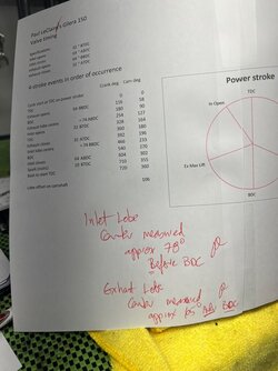
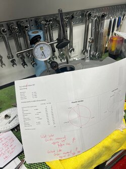


 . I didn’t know there was so much overlap in valve events, past the TDC and BDC. I guess they’re only open a little bit at those points but it’s interesting. No wonder it doesn’t need to be perfect.


