wanted - moto giro bike

So, the speculation by Piet and myself that the overlap is centred around TDC is absolutely spot on. Exactly 32° before and after.

The diagram I posted earlier is also correct except my estimation of 100° as the angle between the cam lobes was a little off. It's actually 106°. I've edited the diagrams to correct that slight error. If Paul uses that diagram as an assembly guide, the cam timing will be correct.

It's nice to get to the bottom of a mystery and finally have all the answers :)
You're excused this time sonny, don't let it happen again... :LOL:

piet
 
What I find really funny is how often I see this 107 valve timing number as THE SPECIAL SECRET discovered by thousands of testing hours number to try for when dialling cam timing on various bike tuning sites all over the world.
 
A lot for me to absorb. I am still stuck on the equal height tappet thing. Yes there is an intermediate gear. The cam can be removed and installed with the crank in place. I put the crank at TDC then slotted the cam into place. Nearly midnight here and U start a couple of days long trial in the morning. Likely can’t get back to the Gilera motor until later in the week. Thanks so much for the help and info!!!!!!
Don't worry, he lost me after "OK Paul"
 
thanks so very much, Cam, Piet, Ari in Finland for sending me the cam timing manual specs, and all you other contributors.

great learning process for me, I clearly had no idea what I was doing when I started. For all the numerous motorcycle and car engines I have built over the years, cam timing for me has always been lining up the factory marks and moving on. The most complicated cam timing I had ever done was slotting cam gears and moving the timing a few degrees one way or the other, but still from factory reference marks. Faced with this situation of no marks at all, on an engine I was not confident had been loosely assembled correctly by whoever was in the engine previously, and the engine never having been started since prior re assembly, I needed to go back to first principles. This forced me to confess my ignorance and really look at the four strokes, overlap, the 2 to 1 ratio between the crank and the cam, the 720 degrees of the four stroke cycle, etc., all the stuff I had never really given much thought to. It also turned out that the cam timing as I received the engine was not correct, so copying what I took out of the motor did not work either.

however, I have my small battery powered metal engraver sitting here on my desk, and the cam gear, idler gear, and crank gear are all geting marks engraved once I get this thing right!!!!!!! I will be refering to Cam's very helpful diagram. I have to confess that while several of you were completely correct in your prior instructions to me to equalize the cam lobes, but I simply could not visualize what was trying to be explained to me......:unsure::unsure:

will report back with photos after I crack the engine case, set the cam timing properly, and close the case again. Unfortunately work commitments intrude, may be a couple of days before I can get back to this. I will check final results with a degree wheel and dial indicator just to be sure.

Great bunch of people here. I really, really really appreciate all the help. Also, I have received several emails and some direct messages of how much people have been enjoying following along in this learning process, despite this not being a Laverda engine.

my heartfelt thanks!!

Paul LeClair
 
Considerations include that the degrees specified are based on a particular rocker clearance, etc., but i think I can figure out how to accommodate that even working directly from the tappets riding directly on the cam.

Don't confuse yourself with any of that stuff Paul. You don't need to worry about the special valve clearance for the cam timing. It's not relevant to engine assembly. It only comes into play once the engine is fully assembled with head torqued down, and only then if you want to check the opening and closing times.

I actually wouldn't bother with opening and closing times because they're rarely identical to the camshaft specs. A couple of thou deviation in the cam profile (due to manufacturing tolerances) can make a big difference in the opening and closing figures. It'll only mess with your head and have you second-guessing yourself if you find such deviations. A way more accurate method to check the cam timing is to use the lobe centres (point of maximum valve lift) as a reference. Refer below for the lobe centre numbers.

The best way to measure camshaft position is to put a dial gauge somewhere (on a tappet or rocker) to measure valve train lift. I'd suggest you do it on the tappets before you assemble the top end of the engine. That way if you've cocked it up, there's less disassembly to correct it.

First, zero your crankshaft degree wheel at TDC (find TDC by locating the big end in the centre of the cylinder opening). Then check the lobe centres with a degree wheel. To find lobe centres, use the same principle as finding TDC with a piston stop. Measure the same amount of lift either side of the maximum and note the reading on the degree wheel for each point. The point of maximum lift (lobe centre) is half way between them. You don't need to be super precise. You only need to make sure you're on the right gear tooth, which are spaced at 21° crank degrees apart. So a few degrees inaccuracy won't matter.

If you're not confident about your assembly of the timing gears, it might give you peace of mind to do a trial assembly with just a couple of bolts holding the crankcase halves together. Once you've confirmed that the timing gear engagement is correct, open the case up and punch timing marks on the gears for next time. Seal the crankcase joint with your favoured brand of sealant and close it up again for the final time.

With the specified cam timing for your engine, the lobe centres are (measuring ATDC in the 720° cycle)
Exhaust lobe centre 254° ATDC
Inlet lobe centre 466° ATDC

Or if you prefer the conventional notation
Exhaust lobe centre 74° ABDC
Inlet lobe centre 74° BBDC

This assumes the lobes are symmetrical in shape (same slope on opening and closing ramps) which most are, and yours appear to be.

You'll note that the lobe centre figures are symmetrical about BDC. That makes sense because all the valve timings are symmetrical.

Note: The attached spreadsheet calculates all the valve events for your specific engine, but it'll work for any 4 stroke. Just put the valve timing specs (opening and closing times) in the specifications list at the top of the sheet and it'll all work itself. The timing diagram charts will readjust to illustrate the angles at which things happen on the degree wheel.
 

Attachments

Last edited:
Don't confuse yourself with any of that stuff Paul. You don't need to worry about the special valve clearance for the cam timing. It's not relevant to engine assembly. It only comes into play once the engine is fully assembled with head torqued down, and only then if you want to check the opening and closing times.

I actually wouldn't bother with opening and closing times because they're rarely identical to the camshaft specs. A couple of thou deviation in the cam profile (due to manufacturing tolerances) can make a big difference in the opening and closing figures. It'll only mess with your head and have you second-guessing yourself if you find such deviations. A way more accurate method to check the cam timing is to use the lobe centres (point of maximum valve lift) as a reference. Refer below for the lobe centre numbers.

The best way to measure camshaft position is to put a dial gauge somewhere (on a tappet or rocker) to measure valve train lift. I'd suggest you do it on the tappets before you assemble the top end of the engine. That way if you've cocked it up, there's less disassembly to correct it.

First, zero your crankshaft degree wheel at TDC (find TDC by locating the big end in the centre of the cylinder opening). Then check the lobe centres with a degree wheel. To find lobe centres, use the same principle as finding TDC with a piston stop. Measure the same amount of lift either side of the maximum and note the reading on the degree wheel for each point. The point of maximum lift (lobe centre) is half way between them. You don't need to be super precise. You only need to make sure you're on the right gear tooth, which are spaced at 21° crank degrees apart. So a few degrees inaccuracy won't matter.

If you're not confident about your assembly of the timing gears, it might give you peace of mind to do a trial assembly with just a couple of bolts holding the crankcase halves together. Once you've confirmed that the timing gear engagement is correct, open the case up and punch timing marks on the gears for next time. Seal the crankcase joint with your favoured brand of sealant and close it up again for the final time.

With the specified cam timing for your engine, the lobe centres are (measuring ATDC in the 720° cycle)
Exhaust lobe centre 254° ATDC
Inlet lobe centre 466° ATDC

Or if you prefer the conventional notation
Exhaust lobe centre 74° ABDC
Inlet lobe centre 74° BBDC

This assumes the lobes are symmetrical in shape (same slope on opening and closing ramps) which most are, and yours appear to be.

You'll note that the lobe centre figures are symmetrical about BDC. That makes sense because all the valve timings are symmetrical.

Note: The attached spreadsheet calculates all the valve events for your specific engine, but it'll work for any 4 stroke. Just put the valve timing specs (opening and closing times) in the specifications list at the top of the sheet and it'll all work itself. The timing diagram charts will readjust to illustrate the angles at which things happen on the degree wheel.
There may be no stupid questions but I guess there are stupid answers (#419) I thought 106 degrees ATDC was the same as 74 degrees BBDC, my apologies, I defer to the experts which clearly I am not.
Stu
 
thanks Cam, I will measure lobe centers as suggested when I am next able to get back out to the garage. I am going to have to give serious consideration to retirement, continuing to work is messing with my hobby time.
 
Yeah. I retired a few years ago. I've got that much stuff to do around home that I dunno how I ever found time to go to work. It's good having no time constraints but the pay (in my case) is pretty lousy.

What's that saying? Something like ... Nobody on their death bed ever said "I wish I'd spent more time at work".
 
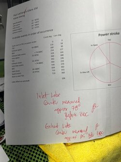
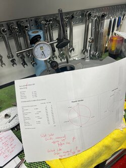
I couldn't take the suspense, will just have to stay up even later preparing for my second trial day tommorow. Out to the garage, dial indicator was already set up on a tappet, degree wheel was still on the crank. Quick measure of lobe centers, way bloody off. Suprisingly how quickly a fresh new engine assembly comes apart, split the cases, moved the cam gear two teeth calculated as roughly 21 degrees per tooth, stuffed the case halves back together, and re measured.

Didn't get an absolutely exact result, some degree of error in my home printed degree wheel and $10 dial indicator.

Measured inlet cam lobe center at approximately 78 degrees Before Bottom Dead Center. Was calculated in Cam's spreadsheet to supposed to be 74 BBDC

Measured exhaust lobe center at approximately 65 degrees After Bottom Dead Center. Was calculated in Cam's spreadsheet to supposed to be 74 ABDC

opening and closing are also not exact to the spreadsheet, but relatively close

I am out 4 degrees on inlet cam lobe center, and 9 degrees on exhaust lobe center, as close as I can measure. Total combined error 13 degrees, and moving one more cam gear tooth would be 21 degrees, now frying my brain trying to figure out whether to move one more cam gear tooth, and if so, in which direction of rotation........ or whether to call it good?
 

Attachments

  • timing 1.jpg
    timing 1.jpg
    109.4 KB · Views: 11
  • timing 2.jpg
    timing 2.jpg
    145 KB · Views: 11
So expressing the lobe centers in conventional form, what you were aiming for was 106/106 and what you have is 102/115

I'd leave it at that. If it was a race engine I'd be playing around with offset keys as the "one tooth" movement is too great.
But that will do.
 
So expressing the lobe centers in conventional form, what you were aiming for was 106/106 and what you have is 102/115

I'd leave it at that. If it was a race engine I'd be playing around with offset keys as the "one tooth" movement is too great.
But that will do.
👍
 
Fascinating. Will be most useful when we get into my son's 175 Gilera, which is however supposedly a running engine.
One must presume that 150 and 175 timing is the same.
If anybody out there has tech docs specific to the 175, it would be most useful.
 
So if Paul moves it one tooth, it would be out 17deg inlet, 12deg on exhaust? So is now as good as it can be?
Great spreadsheet Cam, especially the pictures😁. I didn’t know there was so much overlap in valve events, past the TDC and BDC. I guess they’re only open a little bit at those points but it’s interesting. No wonder it doesn’t need to be perfect.
Hopefully Paul’s case finishes early so we can all get the next episode… this is way better than TV 🤣
 
  • Like
Reactions: Jo
So if Paul moves it one tooth, it would be out 17deg inlet, 12deg on exhaust? So is now as good as it can be?
Great spreadsheet Cam, especially the pictures😁. I didn’t know there was so much overlap in valve events, past the TDC and BDC. I guess they’re only open a little bit at those points but it’s interesting. No wonder it doesn’t need to be perfect.
Hopefully Paul’s case finishes early so we can all get the next episode… this is way better than TV 🤣
what I want to know is where does the turbo fit in the picture!
 
I am out 4 degrees on inlet cam lobe center, and 9 degrees on exhaust lobe center, as close as I can measure. Total combined error 13 degrees,
That's not a cumulative error Paul. The cam lobes are on the same shaft so they move together. As a lawyer you should understand the difference between concurrent and consecutive sentences ;)

I reckon it's close enough. Your inlet cam is slightly advanced and your exhaust cam is slightly retarded. If you go a tooth either way one of them will be miles out. You may have a different camshaft in your engine than the one you got the specs for.
 
Fascinating. Will be most useful when we get into my son's 175 Gilera, which is however supposedly a running engine.
One must presume that 150 and 175 timing is the same.
If anybody out there has tech docs specific to the 175, it would be most useful.
Hi Paul

best online manual resource I was referred to is https://www.rpw.it/Documentazione.htm I just checked, there are a couple of 175 manuals, and cam timing in the 175 manual seems to me to be exactly the same as my 150, but have a look for yourself.

Paul LeClair
 
Slightly advance inlet cam will give you a nice midrange boost anyway! Not sure about advancing exhaust, but I set my 5/C cam about 5 deg advanced 9which of course also advances the ex by the same amount)
 
Back
Top