Wiring diagram & Ignitech

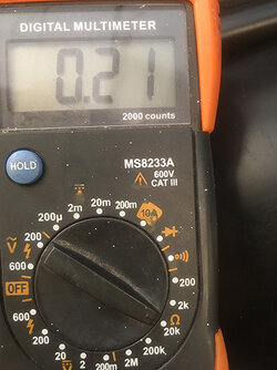
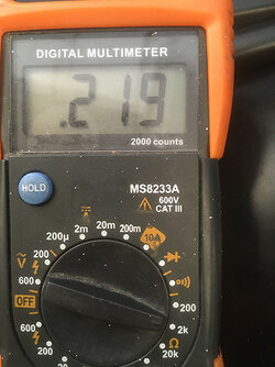
I tested the pick-ups for resistance today and they all came in at 0.21 or 0.216 depending which scale you set but the point is they are all the same and no shorts.
I've no idea how you tested them, or what device you used but those values are unusual. Did you measure with the pickups disconnected from the rest of the ignition system? The resistance of each isolated pickup should be as I previously stated, around 60 ohms.

You could go one step further and check that there is a very small voltage appearing on each pair of pickup wires when you crank the engine - it's been ages since I worked on a bike with original pickups but it's a small value, maybe 2-4 volts depending on your meter's sensitivity.

would an electonic timing gun, of the type which uses a sensor that clips round the HT lead, flash or not.
No - if the plug doesn't spark then there's probably too small a pulse to fire the strobe.

It really is worth fitting brand new plugs - and make sure you earth them when cranking the engine. I'm not sure how an Ignitech handles unearthed plugs - but it's a good way of knackering BTZ and DMC units.

I'd strongly recommend you don't reprogramme the Ignitech - given the bike ran previously the setup must be good. You are looking for a wiring fault.

I'd echo Steve's point about reversed connections on one trigger. Clearly things have developed since the original fault. It's very difficult to solder adequately on to the old wiring. Corrosion/verdigris on the conductor strands can easily result in a dry joint. Looking at your photo of the triggers it seems that you haven't touched the wiring at that end? Ordinarily I would expect to find flaking insulation there too.
 
all good points. I tested the wires/pick-ps with the multi meter set to Ohms and the 20k scale ( I think it's now 8 hours later and short term memory hey ho. ) My "rewiring" conisted of removing the 6way connector at the harness end. Removing the decayed insulation from each wire one at a time cleaning the existing wire core from the point where it became bad which starter about 3" outside the pick uphousing, where it goes under the engine but varied from wire to wire, with electrical cleaner and isoproprinol till they were back to shiny copper then checking with the multimeter that there was good conduction and re-insulating the wire with an appropriate colour heat shrink so as not to get them mixed up in future, so in each pair one wire would be insulated black and the other red yellow or black. they were then heat shinked together in pairs with clear heat shrink. and crimped back to a new connector using the photos I took with my phone of the old connectors. There was no soldering as I don't have quite the steady hand I used to have. the word Re-wiring I guess is not totally acurate but it saved all this explanation. After this the bike ran well ( or as well as I think could be expected ) on 2 cylinders it could be started first try and would tick over slightly lumpily as you would expect with only 2 out of three firing. This was with the plugs that were in it when purchsed. Can I repeat however that the bike had brand new plugs fitted last week a couple of days after it refused to start on the right hand cylinder " for good measure" these were provided with the bike along with a few other spares and are NGK.
I have not at any point tried to start the bike with any plug unearthed as having the timing light means I don't need to see a spark to know if that plug is sparking or not. I have a number of bikes with various electronic ignitions ( OE on the trident 900, Boyer Bransden on the T150v and B44 Motoplatt on the GAS GAS ) and have always understood that running the ignition with the plugs unearthed can be bad for them. I have taken them out to inspect them between sessions however and found the right one ( when it was the only one not working ) to be wet but not black. I have not yet checked them since the others stopped working but will do so on Friday. I will be investigating the polarity suggestion on Friday also as despite my colour coding there's always room for a mistake with me. especially as one pair are both black!
I agree with your suggestion about re-programming as, like you say, it was running well with the programming as it is, my only interest in connecting the computer to the bike would be to try and gleen any information possible about the functionality of the pick ups. The battery BTW is producing 12.9v, is also less than 2 months old and is turning the bike over at very healthy pace. I mention this because the previous owner told me that the ignition becomes crap if the battery voltage drops so someone may have been about to suggest this. I have probably missed something here and I appreciate your attempts to help and useful suggestions so ask anything you like and I will endevour to answer or find out the answer,
once again thanks for your assistance.
 
Last edited:
Do Redax Hall effect pickup and sensor plates for 120s fit without doing the whole ND alternator fitout? It's a shame the Igni box is not Hall effect, as going for a completely new (and much better) Hall over inductive pickup system would negate the probs you're having now. But then, there is the great satisfaction of finally solving a long-term enigma :)
 
Do Redax Hall effect pickup and sensor plates for 120s fit without doing the whole ND alternator fitout? It's a shame the Igni box is not Hall effect, as going for a completely new (and much better) Hall over inductive pickup system would negate the probs you're having now. But then, there is the great satisfaction of finally solving a long-term enigma :)
120's dont need upgraded charging kit, (or all series 2 Donks)(y)
 
Do Redax Hall effect pickup and sensor plates for 120s fit without doing the whole ND alternator fitout? It's a shame the Igni box is not Hall effect, as going for a completely new (and much better) Hall over inductive pickup system would negate the probs you're having now. But then, there is the great satisfaction of finally solving a long-term enigma :)
120s have pickups on the left hand side.
Paul
 
Sorry but I'm very suspicious of the quality of your pickup rewire. I'll give you a 10 for diligent cleaning of the copper strands but if I understand correctly, you've relied on heat shrink to hold the original and new conductors together? The current and voltage generated by the pickup triggers is very small. So anything other than a soldered or crimped connection will cause problems.

A twisted connection of the wires with heatshrink would be a small improvement but unlikely to withstand the hostile environment under the engine for long!

I keep banging on about the pickup resistance reading because that will provide a reasonable indication of the state of your connections. Are you using a digital or analogue meter? Pick a scale that will enable you to read 60 ohms

Have you removed each pickup and closely inspected the wiring? Insulation failure usually happens there too. Easy for a bare wire to short out on the housing. There are some tight corners for the wiring to negotiate too. Also, I'm assuming that you have checked the trigger /rotor airgaps?

Apologies for assuming limited electronic ignition knowledge... but it's often the case that something gets overlooked by assuming rather than asking the question!
 
Sorry but I'm very suspicious of the quality of your pickup rewire. I'll give you a 10 for diligent cleaning of the copper strands but if I understand correctly, you've relied on heat shrink to hold the original and new conductors together? The current and voltage generated by the pickup triggers is very small. So anything other than a soldered or crimped connection will cause problems.
I don't think you have understood me correctly Rob. There is no joining of wires and I cerainly wouldn't trust just heat shrink to do that. There is nothing wrong with the actual wires themselves ( other than a bit of verdigree which can be removed ) all I've done is removed all the brittle and deteriorated insulation and replaced it with heatshrink in more helpful colours and then put a new 6 way connector back on the end again by crimping. There are no new wires involved, just restoring and refitting of the old ones.
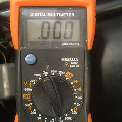
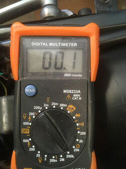
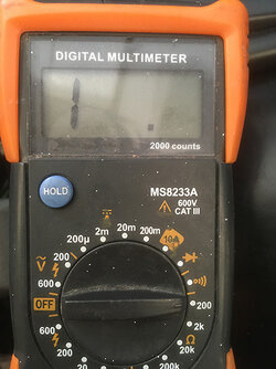
With regard to measuring of resistance, I have a digital Meter, I have tried every scale, there is nothing that will produce 60ohms. The pick-ups all give the same result the one's for the cylinders that were firing and the one that wasn't. Though of course non of them are now. Hopefully you can see pics of the result on every available scale below. What I would say is that on the 200 scale ( Image 6 ) it does not go straight to 1 . imediately when connected but flashes through a few numbers first, one of which is 68.something. it's too quick for me to read the whole thing before it's gone. Resistance is the same in both directions and there is no continuity between engine casings and any of the pins in the connector block.
I don't know why you need to remove each pick-up to closely inspect the wiring. it's right there. I've pulled the wires out so that they come directly out of the casing not through the rubber grommit, so that I could determine where the decay started as accurately as possible, and you can see that on my previous images, the wiring inside the cases is pretty good. it certainly isn't shorting to anything or I would get a reading between the pins of the connector and the engine casings. The poor state of the insulation really started under the engine.
Don't worry about assuming my ignorance Rob I'd rather no stone was left unturned in that direction in my case there's always the possibilty of a slug.
IMG_1.jpgIMG_2.jpgIMG_3.jpgIMG_4.jpgIMG_5.jpg
 
Rob I have re-read my post again and what I think fooled you was where I said I heatshrinked them together in pairs, but what that is referring to is that once i'd re-insulated each wire with the appropriate colour heat shrink I then placed a larger piece of clear heatshrink over the two wires from each pickup to keep them together in a pair. Clear heatshrink over coloured heatshrink. With one of each pair being black I felt that would make it easier not to get the black wires mixed up at the other end. Sorry for the confusion that caused.
 
On the 200 Ohm scale a reading of 1 indicates you have more than the upper parameter i.e more than 200 Ohm. Therefore a reading of 0.22 on the 2K scale indicates 220 Ohm. (Plus or minus the quality of the meter).
Edit: shonky conversion 😳
 
Last edited:
Rob has good points to work with, the oem Bosch pickups read in the 218 to 220 Ohm span. DMM resolution diminishes as your maximum scale is increased looking for 220Ohms on 20,000 ohm scale your going to lose resolution The .219 is set against a maximum reading of 2,000 as a ratio .219 of 2000 is 219 Ohms, low cost DMM have limits in readout function and how the measurements are actually done internally.

VR pickup has two signals from the paired wires, a postive going leading edge and a negative going trialing edge as impulse cam approaches and departs the VR pole face or faces. Therefore the paired pup output wires are polarity sensitive, you will get some strange effects on ignitions with a reversed pup polarity. You can test for polarity by DMM on volts, bring a ferrous item towards the pole and get a positive output voltage take the ferrous item away and the DMM will indicate a negative going DC voltage, use a low volts range on the DMM and note the polarity segment on the DC scale readout.

Not so keen to get involved with the ignition module connection and operation you have there, the lads are doing that all in all. Much is about covering all aspects of a fault or faults location, this can mean covering obvious aspects even though you are competent in many things, no insult to cover the obvious, can help cover all aspects, in place of assuming and missing the very solution to the success of rectification, should that ramble make sense..HTH j.
 
Last edited:
what I think fooled you was where I said I heatshrinked them together in pairs,
Yep - thanks for clarifying.

So we're still left with the conundrum of high resistance on all 3 pickups. Either a duff meter or rowdypat's comment applies! I assume you're measuring at the pins on the 6 way plug you recrimped?

You can test for polarity by DMM on volts, bring a ferrous item towards the pole and get a positive output voltage take the ferrous item away and the DMM will indicate a negative going DC voltage, use a low volts range on the DMM and note the polarity segment on the DC scale readout.
Leaving the resistance readings to one side for a moment, you may like to carry out this check suggested by John. If you do see positive and negative voltage pulses then the trigger is working. And you can verify the wiring polarity too.
You do (in my experience) need to move a screwdriver blade (or whatever) quickly to the pickup polepieces and then away
 
So we're still left with the conundrum of high resistance on all 3 pickups. Either a duff meter or rowdypat's comment applies! I assume you're measuring at the pins on the 6 way plug you recrimped?
Yes I am Rob. the meter, whilst not a particularly expensive model has not to my knowledge let me down before, so I'll try iis_iis's polarity test next. although I'm wondering where the neccessary third hand is going to come from. Just to further my education chaps what does the VR in VR pickup stand for?
 
Today I've done the test for polarity and got exactly the opposite on all the pickups ie approaching gives me a negative voltage and receeding gives a positive one: all the pickups were the same, so all are working - no "odd one out"- but I'm guessing which pin I should have each probe of the DMM on when doing the test. Should I have the com probe on the white wire or the white with black trace wire? I also get the feeling that the bottom Pickup is a tad further out than the other two from trying to slide a screwdriver across the face so will check that in the morning as well If I can find the feeler gauges.
 
Last edited:
To get round the question of which wire is providing what polarity, this method explained by Piet might be the best approach.

I wonder if your meter battery is causing the readings issue?
 
Are we talking about a series 2 or series 1 pup configuration? Looking at the bike photo is appeared as a series 2 ( 120 ), series 2 pups are 220 Ohm, series 1 are in the 55 to 60 Ohm span.

Variable Reluctor, VR. permanent magnet with copper winding around it, as the magnetic field is distorted by ferrous metal near the pole face ( soft or silicon steel that does not permanently magnetize ), ie like a small generator produces its own signal voltage without external power.

Rokka the polarity test you did was reversed referenced. In electronics we have a "reference" point for measurements, like a battery with two posts, one is labeled + positive and one - negative, this impossible in electrical engineering. You measure one post against the other, to obtain a reading, one post becomes the reference or 0V ( can be the negative fly lead from your DMM ) you then read the second post with Red DMM and have say +12V if you reverse the connection of dmm leads the post terminal polarity reverses. Which is what you had, reversed DMM connection and the implied reference point was the active output signal from the pickup ( "Pup pickUP PUP ) your ignition module should indicate the reference connection point, could be 3 wire connections are connected internally as common to DC negative ( yes i know ist not negative actually grin ) power supply or the dreaded term "earth".

May not be all that clear, not many ways to make it more clear without doing a lab class after the theory lesson, yes i taught electrical engineering at college...for 10 years. Students did like my classes eventually though not immediately, terms of reference were high on the list of first principles imposed. HTH j
 
Last edited:
To get round the question of which wire is providing what polarity, this method explained by Piet might be the best approach.

I wonder if your meter battery is causing the readings issue?
This may not work with all electronic ignitions Rob, in some designs, you need a pre load signal to saturate a coil before the spark can occur. Usually the cold crank rotational sequence, OEM ignitions on Laverda are analouge and will work on Piets test routine. Not certain it will work on digital systems. HTH

Digital design will need this pre load signal in one form or another, this is why i designed the two iis self test switch positions, E for Encoder and F for Fire all plugs. HTH j.
 
so what i'm getting from you two is that as the owner of a 120 triple my PUPs should produce a resistance of between 218 and 220, which is what they are doing. That they should react to the dynamic proximity of a lump of ferrous metal by producing a small + dc voltage as it approaches and a small - voltage as it leaves which it probably is doing as I can't imagine all three having become reversed when I was that careful to indentify the wires to the connector ( I'm not saying it couldn't have happened just that I think on balance that it's unlikely,) and two cylinders ran for almost a week after any wiring. Also testing with the DMM shows continuity but no shorts in the wiring to the PUPs.
where to look next? other than taking the ballast out of the circuit and cleaning the connectors I have not touched the wiring at the coil end. I did remove the battery -to make sure it was absolutely charged- out of the near side by removing the lifting handle etc so did not pull or interfere with any wires doing that. In order to get at the six way connector i had to move the airbox as the cables either side of the connector had been ziplocked to the frame crossmember just in front of the battery at the bottom of it. I had to move quite a bit of wiring to get at the top right airbox locating nut So wiring wise the next thing to check would be the connections to the other side of the sixway connector and from there to the ignition box large connector. I also need to connect to the ignitech box now to find out ( given I have no sparks at all now ) if it's still working at all! and check the wiring from the box to the coils.
 
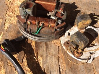
Very early series 1 stator plate for a HKZ with early Mu-Metal shields around the VR's, deleted on later series 1 stator plate, and both had cast in pup housing. 120 type bosch pups, just need a light brush for near showroom refurb... i do not have a high regard for later 220 ohm bosch pups...

Notable is the incoming fly wire insulation degradation with oil and temperature exposure, for both series 1 and 2 pups j
 

Attachments

  • Bosch_pups.JPG
    Bosch_pups.JPG
    237.3 KB · Views: 19
Back
Top