
You are using an out of date browser. It may not display this or other websites correctly.
You should upgrade or use an alternative browser.
You should upgrade or use an alternative browser.
Building my Jota
- Thread starter sideshow
- Start date

GregT
Hero member
- Location
- Christchurch NZ
All the big post classic racebikes I build have full floating rear calipers. 10mm fine thread heim joints with around 15mm of thread engagement stand up to a vigorous rider backing a big bike into corners, If your rider can manipulate the clutch or you have a back torque limiting clutch you get no chatter and the wheel stays in contact with the ground over the typically rough street circuits we have here.I make a front anchor point which is in double shear - a bracket each side of the front heim joint. I really don't want to calculate the load on the torque arm with slicks and a heavy bike - but empirically i can say I've not had one break.
I'd offer cone nuts as an alternative fastening for Astralites. High temp version of nylocs with a metal insert rather than plastic. Bit more secure than plastic too.
I'd offer cone nuts as an alternative fastening for Astralites. High temp version of nylocs with a metal insert rather than plastic. Bit more secure than plastic too.

Tippie
Hero member
- Location
- Dr?bak, Norway
My setup is exactly the same as Quenitn´s. I had the torque arm attached to the calliper bracket with a bolt through the rose joint, but changed and have it between two plates so that it is in line with the centre of the calliper bracket as Greg mentions for his frame ends (my frame end is a bolt through the rose joint), this was to give it more clearance to the swing-arm (was almost touching) and give it a straighter pull. I never use the rear when racing, just when transiting the pits, and only in first gear in car parks etc on the road bike unless on dirt. With the SFC 2 into 1 I had to have a dogleg torque arm before I used the reverse linkage.

sideshow
Hero member
.im a photos sort of person, or drawings sort of person. My brain looses a lot or plain just doesn’t understand words sometimes, they just don’t draw a clear picture in my head.All the big post classic racebikes I build have full floating rear calipers. 10mm fine thread heim joints with around 15mm of thread engagement stand up to a vigorous rider backing a big bike into corners, If your rider can manipulate the clutch or you have a back torque limiting clutch you get no chatter and the wheel stays in contact with the ground over the typically rough street circuits we have here.I make a front anchor point which is in double shear - a bracket each side of the front heim joint. I really don't want to calculate the load on the torque arm with slicks and a heavy bike - but empirically i can say I've not had one break.
I'd offer cone nuts as an alternative fastening for Astralites. High temp version of nylocs with a metal insert rather than plastic. Bit more secure than plastic too.
come what may the rear brake needs to pass a brake test on the rolling road they have at the test station, for the w.o.f in NZ speak and roadworthy in Australian terms So it needs to be solid enough to pass that .
would A tang welded to the underside of the swing arm, say below where the old brake stay bracket for the original brake work ?
sideshow
Hero member
I think I have it sorted now , I have gone further than the chopped exhaust picture earlier , and I think I can go to my original plan of the brake stay going forward to the lower aft engine mount bold. It doesn’t only hang on that , the little offset bracket I made , is such that when the brake is applied it butts up against the mount tang , so the load is shared between the tang and the bolt .the little bracket is in grade 5 Ti and has now been glass blasted . The left one was the prototype I drew and printed. The right side one is the final machined one. I will try take a photo of the set up tomorrow when I have printed the tube bend for the exhaust behind the collector , to see if what I have done works 
Last edited:

piranha-bro2
Hero member
- Location
- Melbourne
Tidy solution, Todd. As for stopping power and roadworthies, don't think you'll have any probs with a std-ish disc and m/cyl setup.

Dellortoman
Hero member
- Location
- Tasmania, Australia
Not much difference between 316 and 304 stainless as far as strength goes. The main difference is that 316 has slightly better corrosion resistance so tends to be the choice for marine environments. They're both what's known as austenitic stainless steel, and both have an ultimate tensile strength (UTS) of around 600MPa, which is comparable to mild steel.What would the tensile strength of 316 stainless be?
As far as bolts are concerned, I'd consider stainless bolts (either 304 or 316) as roughly equivalent to grade 4.6 steel bolts. OK for general stuff like the universal M6 bolts that hold engine covers on, but I wouldn't use them where high strength is required. You'll propbably get away with it most of the time, but for critical applications like brake caliper fixings, I wouldn't replace grade 8.8 bolts with stainless.
Actually, it's not the UTS that's the design criteria, it's the yeild strength. "Yeild" is the stress point at which a piece of steel will permanently deform (ie. beyond its elastic limit). UTS is the point at which it actually breaks apart. The yeild strength is considerably less than the UTS.

motoddrob
Hero member
- Location
- S/W Australia
Thanks CamNot much difference between 316 and 304 stainless as far as strength goes. The main difference is that 316 has slightly better corrosion resistance so tends to be the choice for marine environments. They're both what's known as austenitic stainless steel, and both have an ultimate tensile strength (UTS) of around 600MPa, which is comparable to mild steel.
As far as bolts are concerned, I'd consider stainless bolts (either 304 or 316) as roughly equivalent to grade 4.6 steel bolts. OK for general stuff like the universal M6 bolts that hold engine covers on, but I wouldn't use them where high strength is required. You'll propbably get away with it most of the time, but for critical applications like brake caliper fixings, I wouldn't replace grade 8.8 bolts with stainless.
Actually, it's not the UTS that's the design criteria, it's the yeild strength. "Yeild" is the stress point at which a piece of steel will permanently deform (ie. beyond its elastic limit). UTS is the point at which it actually breaks apart. The yeild strength is considerably less than the UTS.
Very imformative
sideshow
Hero member
Ok so this is what i think Im aiming at, if something is glaringly obvious, please point it out.
First photo
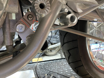
The adaptor tang for the inboard end of the brake stay is held in place by the engine mount bolt. Just above the engine mount bolt you can see a thin red line I have drawn in, on the backside of the adapter tang there is a step, which creates a seat that the bracket sits on the engine mount tang. My theory on this is that when everything is fastened and adjusted , and the rear brake is applied, it wants to pull the torque stay aft, and I think by having the step in the bracket so it sits on the engine mount tang this helps share the load between the bolt and the engine mount tang, by acting as a stop. What shows up looking like a crack in the engine case, is just the shadow created by the workshop lighting over a cast mark. M8 fasteners are used in each end for the Heim joints.
Second photo
This shows the brake stay now able to go above the exhaust , its a bit of an optical illusion but there is 20mm of clearance, which i hope is enough... let me know if that is sufficient.
Now the exhaust looks at a far better angle than when it arrived. I did ask that it got made this short or shorter, but was knocked back by the builder on it, in hindsight that was probably a good thing, as its allowed me to get what is needed and what i want it to look like
all the fasteners in these areas are just build fasteners, nicer and in super duplex and glass blasted
First photo
The adaptor tang for the inboard end of the brake stay is held in place by the engine mount bolt. Just above the engine mount bolt you can see a thin red line I have drawn in, on the backside of the adapter tang there is a step, which creates a seat that the bracket sits on the engine mount tang. My theory on this is that when everything is fastened and adjusted , and the rear brake is applied, it wants to pull the torque stay aft, and I think by having the step in the bracket so it sits on the engine mount tang this helps share the load between the bolt and the engine mount tang, by acting as a stop. What shows up looking like a crack in the engine case, is just the shadow created by the workshop lighting over a cast mark. M8 fasteners are used in each end for the Heim joints.
Second photo
This shows the brake stay now able to go above the exhaust , its a bit of an optical illusion but there is 20mm of clearance, which i hope is enough... let me know if that is sufficient.
Now the exhaust looks at a far better angle than when it arrived. I did ask that it got made this short or shorter, but was knocked back by the builder on it, in hindsight that was probably a good thing, as its allowed me to get what is needed and what i want it to look like
all the fasteners in these areas are just build fasteners, nicer and in super duplex and glass blasted
Attachments


chrisk
Hero member
- Location
- Brisbane, Australia
 Well sorted Todd.
BTW, mate, your left hand is tiny, well groomed nails though

sideshow
Hero member
Im a freak of nature
BTW, mate, your left hand is tiny, well groomed nails though

My 10 year old daughter wanted Dad and Shed time last night, so it was a win win, but bugger me I should have an award for managing to get the photo where her arm was actually still for the nano second in time that there was no movement
GregT
Hero member
- Location
- Christchurch NZ
While I'm not qualified to do an analysis on it, the offset front bracket i don't like. If it's got to be like that, make the offset so that it's hard up against the top edge of the frame bracket. It'll move as it's shown IMO.
All my big bikes use 10mm fasteners both ends of the torque arm. 8mm is IMO, a tad light.
You're lucky having a helper. I have to use blocks of wood....
All my big bikes use 10mm fasteners both ends of the torque arm. 8mm is IMO, a tad light.
You're lucky having a helper. I have to use blocks of wood....
piranha-bro2
Hero member
- Location
- Melbourne
Don't agree, Greg. The rearward drag from an applied rear brake is trying to pull the lug backwards, but its step (invisible) is hard up against the engine mount lug. The only possible weakness would be the lug snapping at the step, but doubtful IMHO.
I use M10 rose joint threads in the rod, but M8s for fastening to caliper mount and frame. The compression effect of the M8 gives more than enough 'grip' (what's the technical term!!) to prevent any mishaps. Tried and true on road, corrugated dirt, racetracks ...
Um, I have been known to be wrong, so happy to have an engineer shout me down (I chose the Ninja just cos I like it)
I use M10 rose joint threads in the rod, but M8s for fastening to caliper mount and frame. The compression effect of the M8 gives more than enough 'grip' (what's the technical term!!) to prevent any mishaps. Tried and true on road, corrugated dirt, racetracks ...
Um, I have been known to be wrong, so happy to have an engineer shout me down
(I chose the Ninja just cos I like it)
hooksey
Hero member
- Location
- Vic , Australia
Mmmm, what about a bigger surface area on one end of brkt and two bolts thru lugg on frame?
Dellortoman
Hero member
- Location
- Tasmania, Australia
If it was my bike, I'd have simply welded a lug onto the underside of the swing arm and bolted the torque arm to that.
Or, used the existing caliper carrier stop system and make an upside-down carrier mounting bracket for an under-slung caliper.
Or, simpler still, leave the caliper where the fastory put it - above the swing arm.
What's the reason for mounting the caliper below the swing arm anyway? I can think of a few reasons NOT to mount a caliper under the swing arm, but no reasons in favour of it. So to me it seems a lot of work for no benefit, but maybe I'm missing something.
Or, used the existing caliper carrier stop system and make an upside-down carrier mounting bracket for an under-slung caliper.
Or, simpler still, leave the caliper where the fastory put it - above the swing arm.
What's the reason for mounting the caliper below the swing arm anyway? I can think of a few reasons NOT to mount a caliper under the swing arm, but no reasons in favour of it. So to me it seems a lot of work for no benefit, but maybe I'm missing something.
sideshow
Hero member
Hi CamIf it was my bike, I'd have simply welded a lug onto the underside of the swing arm and bolted the torque arm to that.
Or, used the existing caliper carrier stop system and make an upside-down carrier mounting bracket for an under-slung caliper.
Or, simpler still, leave the caliper where the fastory put it - above the swing arm.
What's the reason for mounting the caliper below the swing arm anyway? I can think of a few reasons NOT to mount a caliper under the swing arm, but no reasons in favour of it. So to me it seems a lot of work for no benefit, but maybe I'm missing something.
Im doing this so the front and rear brake callipers are the same model, for aesthetics more than anything. I did pose the question in one of my earlier posts about welding a lug to the swing arm, no one answered it , easily missed Im sure. And as I have already made this system I was trying to utilise it. The rear bracket for the calliper and the spacers etc all came with the wheels from Gjis.
So as I have all that I thought it a shame to not use it. I can obviously change the heim joints etc, I think I checked with Red what size they use on their race bikes, so I may have got that wrong.

martymoose
Hero member
- Location
- Sydney, Australia
Royal Enfield 500 single drum brake rear. Pivot bolt for the shoes acts as the anchor bolt, 12mm, goes through a slot in the swingarm. Bike came in with the anchor bolt sheared off. Stuffed the backing plate. Got all new parts, bolted it up, took it for a test ride around the block, snapped the bolt again, locked the rear wheel solid middle of the road. Nice flat spot on the tyre. Poxy heap of Indian shite.
sideshow
Hero member
They come in pretty handy in the shop too, halyards and sheets I have built into boxes for shipping around the world !While I'm not qualified to do an analysis on it, the offset front bracket i don't like. If it's got to be like that, make the offset so that it's hard up against the top edge of the frame bracket. It'll move as it's shown IMO.
All my big bikes use 10mm fasteners both ends of the torque arm. 8mm is IMO, a tad light.
You're lucky having a helper. I have to use blocks of wood....
Attachments


piranha-bro2
Hero member
- Location
- Melbourne
BTW, you can lift your mega even more if you want - the suspension is fully extended in the pics and on the road it's never going beyond that point. Aesthetically I'd like to see a little more upsweep.
Nice little tax dodge those kidling slaves you employ, Todd!
Nice little tax dodge those kidling slaves you employ, Todd!